TOC
TOC
TROUBLESHOOTING & REPAIR | ||
|
|
CONTROL BOARD REMOVAL AND REPLACEMENT (continued)
Return to Section
Return to Section TOC
Return to Master
Return to Master TOC
PROCEDURE
1.Remove input power to the
2.Perform Filter Capacitor Discharge Procedure detailed in Maintenance Section.
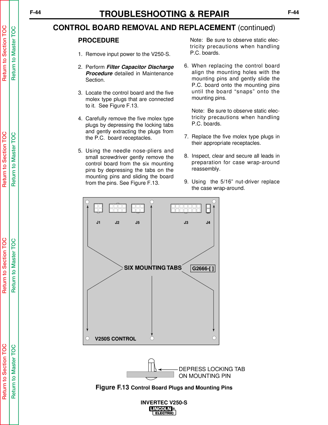
3.Locate the control board and the five molex type plugs that are connected to it. See Figure F.13.
4.Carefully remove the five molex type plugs by depressing the locking tabs and gently extracting the plugs from the P.C. board receptacles.
5.Using the needle
Note: Be sure to observe static elec- tricity precautions when handling P.C. boards.
6.When replacing the control board align the mounting holes with the mounting pins and gently slide the P.C. board onto the mounting pins until the board “snaps” onto the mounting pins.
Note: Be sure to observe static elec- tricity precautions when handling P.C. boards.
7.Replace the five molex type plugs in their appropriate receptacles.
8.Inspect, clear and secure all leads in preparation for case
9.Using the 5/16”
Return to Section TOC
Return to Section TOC
Return to Master TOC
Return to Master TOC
|
|
|
|
|
|
|
|
|
|
|
|
|
|
|
|
|
|
|
|
J1 |
| J2 |
| J5 |
| J3 | J4 | ||
|
|
|
|
|
|
|
|
|
|
SIX MOUNTING TABS G2666-[ ]
V250S CONTROL
![]()
![]()
![]() DEPRESS LOCKING TAB
DEPRESS LOCKING TAB
ON MOUNTING PIN