Section TOC
Master TOC
THEORY OF OPERATION
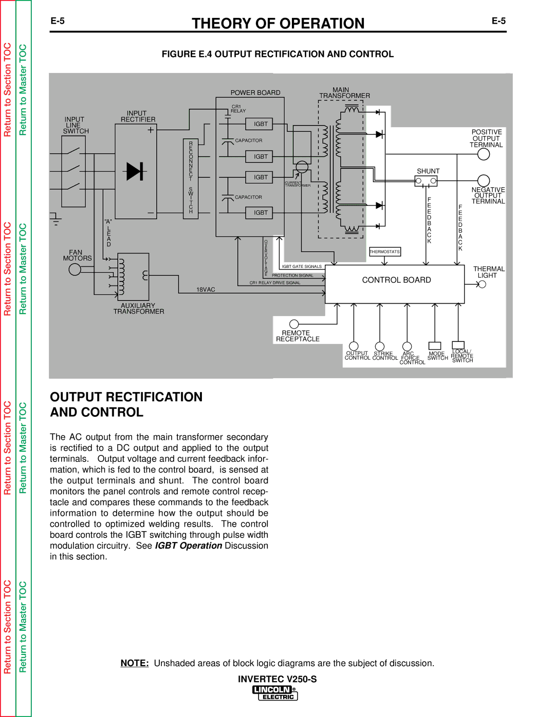
FIGURE E.4 OUTPUT RECTIFICATION AND CONTROL
Return to
Return to Section TOC
Return to
Return to Master TOC
INPUT
INPUTRECTIFIER LINE
SWITCH
"A"
L
E
A
D
FAN
MOTORS
R
E
C
O
N
N
E
C
T
S
W
I
T
C
H
18VAC
POWER BOARD | MAIN |
| |
TRANSFORMER |
| ||
|
|
| |
CR1 |
|
|
|
RELAY |
|
|
|
IGBT |
|
|
|
|
|
| POSITIVE |
CAPACITOR |
|
| OUTPUT |
|
|
| TERMINAL |
IGBT |
|
|
|
IGBT |
| SHUNT |
|
|
|
| |
| CURRENT |
|
|
| TRANSFORMER |
| NEGATIVE |
|
|
| |
CAPACITOR |
| F | OUTPUT |
|
| TERMINAL | |
|
| E | F |
IGBT |
| E | E |
|
| D | E |
|
| B | D |
|
| A | B |
|
| C | A |
O |
| K | C |
V |
|
| |
E |
| THERMOSTATS | K |
R |
|
| |
V |
|
|
|
O |
|
|
|
L |
|
|
|
T | IGBT GATE SIGNALS | THERMAL | |
A | |||
G |
|
| |
E | PROTECTION SIGNAL | CONTROL BOARD | LIGHT |
| |||
CR1 RELAY DRIVE SIGNAL |
| ||
Return to Section TOC
Return to Section TOC
Return to Master TOC
Return to Master TOC
AUXILIARY
TRANSFORMER
REMOTE
RECEPTACLE
| OUTPUT STRIKE ARC |
|
|
| LOCAL/ |
|
| MODE | |||
|
| REMOTE | |||
| CONTROL CONTROL FORCE | SWITCH | |||
| CONTROL |
|
|
| SWITCH |
|
|
|
|
| |
|
|
|
|
|
|
|
|
|
|
|
|
OUTPUT RECTIFICATION
AND CONTROL
The AC output from the main transformer secondary is rectified to a DC output and applied to the output terminals. Output voltage and current feedback infor- mation, which is fed to the control board, is sensed at the output terminals and shunt. The control board monitors the panel controls and remote control recep- tacle and compares these commands to the feedback information to determine how the output should be controlled to optimized welding results. The control board controls the IGBT switching through pulse width modulation circuitry. See IGBT Operation Discussion in this section.
NOTE: Unshaded areas of block logic diagrams are the subject of discussion.