Return to Section TOC
Return to Section TOC
Return to Section TOC
Return to Section TOC
Return to Master TOC
Return to Master TOC
Return to Master TOC
Return to Master TOC
TROUBLESHOOTING & REPAIR |
| |||||||
|
|
|
|
| ||||
|
|
| POWER BOARD RESISTANCE TEST (continued) |
|
| |||
|
|
|
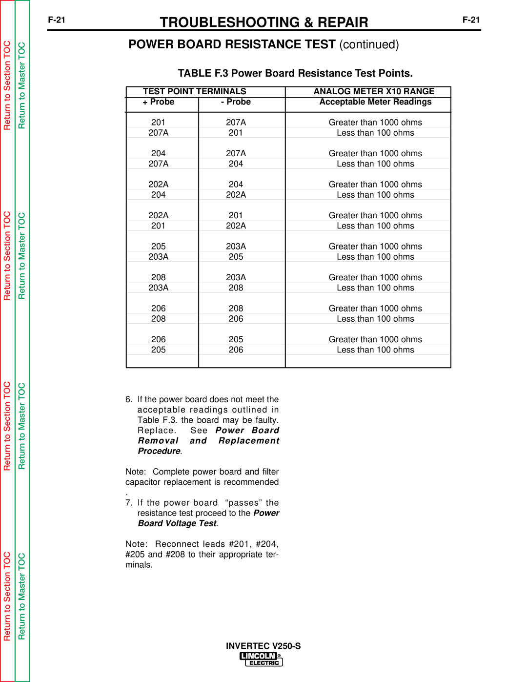
| TABLE F.3 Power Board Resistance Test Points. |
|
| ||
|
|
|
|
|
|
|
| |
|
|
| TEST POINT TERMINALS | ANALOG METER X10 RANGE |
|
| ||
|
|
| + Probe |
| - Probe | Acceptable Meter Readings |
|
|
|
|
|
|
|
|
|
|
|
|
|
| 201 |
| 207A | Greater than 1000 ohms |
|
|
|
|
| 207A |
| 201 | Less than 100 ohms |
|
|
|
|
| 204 |
| 207A | Greater than 1000 ohms |
|
|
|
|
| 207A |
| 204 | Less than 100 ohms |
|
|
|
|
| 202A |
| 204 | Greater than 1000 ohms |
|
|
|
|
| 204 |
| 202A | Less than 100 ohms |
|
|
|
|
| 202A |
| 201 | Greater than 1000 ohms |
|
|
|
|
| 201 |
| 202A | Less than 100 ohms |
|
|
|
|
| 205 |
| 203A | Greater than 1000 ohms |
|
|
|
|
| 203A |
| 205 | Less than 100 ohms |
|
|
|
|
| 208 |
| 203A | Greater than 1000 ohms |
|
|
|
|
| 203A |
| 208 | Less than 100 ohms |
|
|
|
|
| 206 |
| 208 | Greater than 1000 ohms |
|
|
|
|
| 208 |
| 206 | Less than 100 ohms |
|
|
|
|
| 206 |
| 205 | Greater than 1000 ohms |
|
|
|
|
| 205 |
| 206 | Less than 100 ohms |
|
|
|
|
|
|
|
|
|
|
|
6.If the power board does not meet the acceptable readings outlined in Table F.3. the board may be faulty. Replace. See Power Board
Removal and Replacement Procedure.
Note: Complete power board and filter capacitor replacement is recommended
.
7.If the power board “passes” the resistance test proceed to the Power Board Voltage Test.
Note: Reconnect leads #201, #204, #205 and #208 to their appropriate ter- minals.