Section TOC
Master TOC
TROUBLESHOOTING & REPAIR | ||
|
|
OUTPUT DIODE ASSEMBLY REMOVAL AND REPLACEMENT
(MACHINE CODES ABOVE 10150)
(continued)
Return to
Return to Section TOC
Return to
Return to Master TOC
PROCEDURE
1.Remove input power to the
2.Perform Filter Capacitor Discharge Procedure detailed in Maintenance Section.
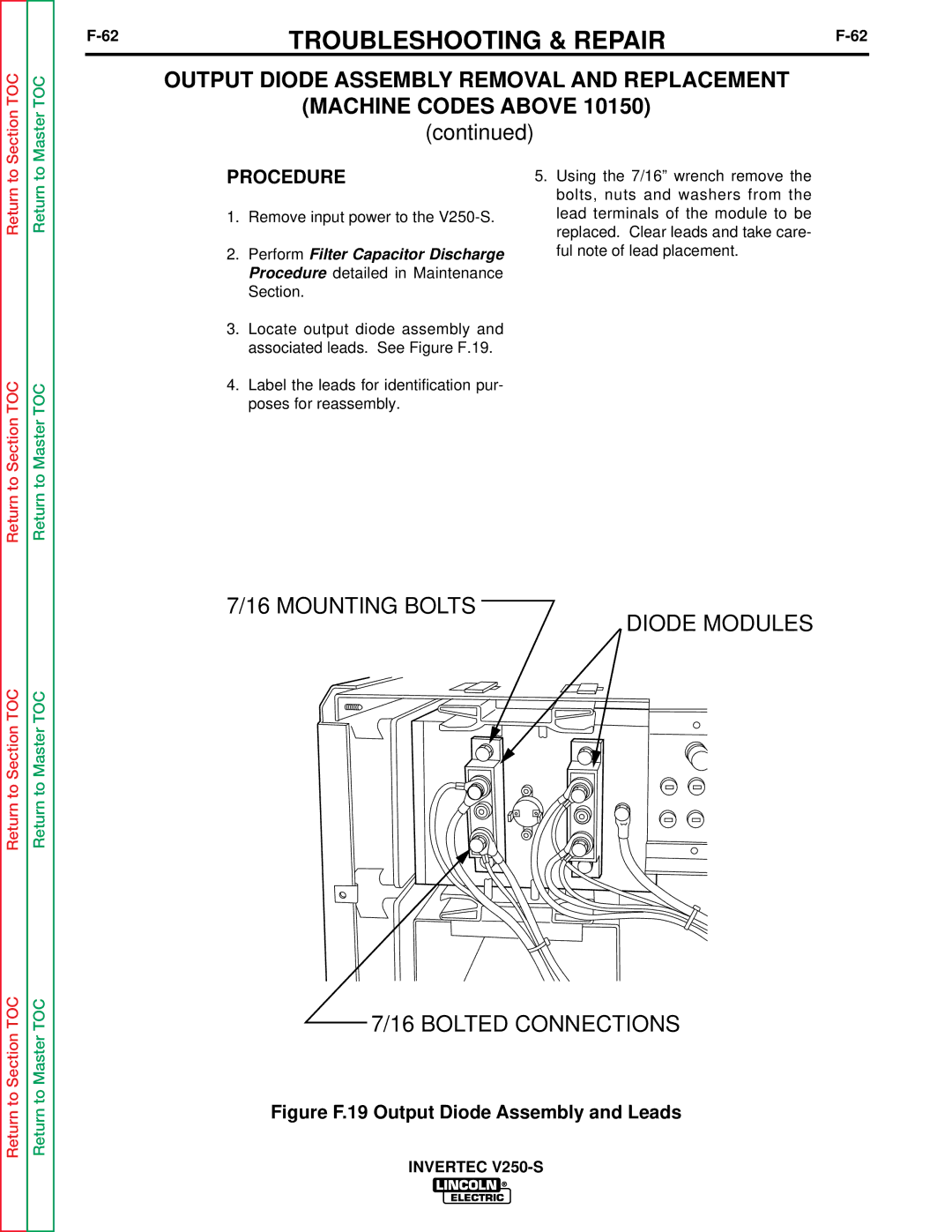
3.Locate output diode assembly and associated leads. See Figure F.19.
4.Label the leads for identification pur- poses for reassembly.
5.Using the 7/16” wrench remove the bolts, nuts and washers from the lead terminals of the module to be replaced. Clear leads and take care- ful note of lead placement.
Return to Section TOC
Return to Section TOC
Return to Master TOC
Return to Master TOC
