MultiVOIPTM FX
Record of Revisions
S000415A
Patents
Trademark
Contents
Contents MultiVOIP FXS User Guide
Overview
About This Manual
MVPFXS-8/16/24 Chassis
MultiVOIP FXS User Guide Overview
Overview MultiVOIP FXS User Guide
Logging with SysLog
Channel-Operation LEDs
MultiVOIP Front Panel LEDs
Computer Requirements
Specifications
Related Documentation
Installation at a Glance
Quick Start Guide
Task
MultiVOIP Startup Tasks
All MultiVOIP models
Phone/IP Details *Absolutely Needed
Analog Phone Parameters
Identify Remote Voip Site to Call
Placement
Command/Control Computer Setup Specs & Settings
MultiVOIP FXS Quick Start Guide Command PC & Voip Hookups
Quick Hookup for MVPFXS-8/16/24
Command PC & Voip Hookups MultiVOIP FXS Quick Start Guide
Changing the IP Address through the Console Connection
Auxiliary Software Issues MultiVOIP FXS Quick Start Guide
Phone/IP Starter Config MultiVOIP FX Quick Start Guide
MultiVOIP FXS Quick Start Guide Phone/IP Starter Config
Press Enter
Printenv at
Phone/IP Starter Config MultiVOIP FX Quick Start Guide
MultiVOIP FXS Quick Start Guide Phone/IP Starter Config
MVPFXS-24 MVPFXS-16 MVPFXS-8
Phone/IP Starter Configuration
MultiVOIP FXS Quick Start Guide Phonebook Starter Config
Phonebook Starter Configuration with remote voip
North America Long-Distance Example
Euro, National Call Example
North America Long-Distance Example Seattle-Chicago system
Phonebook Starter Config MultiVOIP FXS Quick Start Guide
Euro, National Call Example London/Birming. system
Euro, International Call Example Rotterdam/Bordeaux system
Remove Prefix field, enter the initial PBX access digit 8 or
Inbound Phonebook
North America Euro, National Call Long-Distance Example
Phonebook Tips MultiVOIP FXS Quick Start Guide
Phonebook Tips
= 1-second pause
MultiVOIP FXS Quick Start Guide Phonebook Tips
Many PBX systems
Phonebook Example MultiVOIP FXS Quick Start Guide
Phonebook Example An MTU/MDU Application
Inbound Phonebook Outbound Phonebook
MultiVOIP FXS Quick Start Guide Phonebook Example
Inbound Phonebook
Phonebook ExampleMultiVOIP FXS Quick Start Guide
Phonebook Worksheet
Enlarged Phonebook Worksheet
Connectivity Test MultiVOIP FXS Quick Start Guide
Connectivity Test
MultiVOIP FXS Quick Start Guide Connectivity Test
Quick Start Instructions MultiVOIP FXS User Guide
Troubleshooting
Mechanical Installation and Cabling
General Safety
Safety Warnings
Lithium Battery Caution
Ethernet WAN Ports Caution Safety Warnings Telecom
Unpacking Your MultiVOIP
MultiVOIP FXS User Guide Mechanical Installation & Cabling
Unpacking the MVPFXS-8/16/24
Rack-Mounting MVPFXS-8/16/24
Rack Mounting Instructions for MVPFXS-8/16/24
MultiVOIP FXS User Guide Mechanical Installation & Cabling
Bracket Attachment for Rack Mounting MVPFXS-8/16/24
Inch Rack Enclosure Mounting Procedure
Cabling for the MVPFXS-8/16/24
Cabling Procedure for MVPFXS-8/16/24
PBX
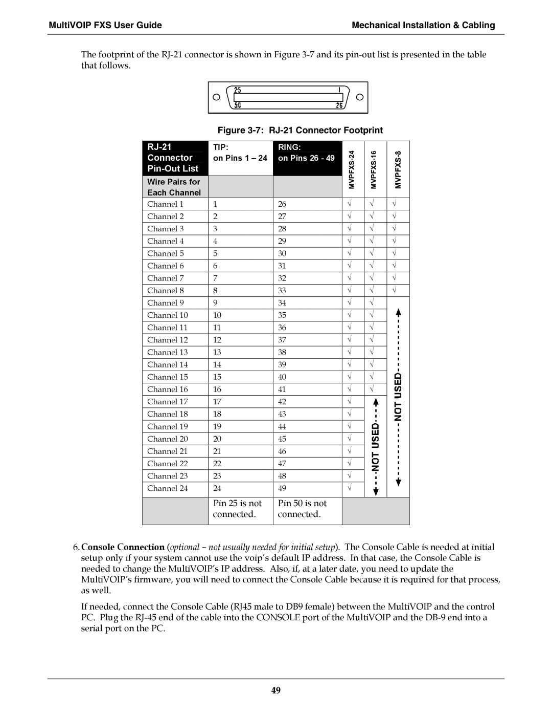
RJ-21
Mechanical Installation & Cabling MultiVOIP FXS User Guide
MultiVOIP & Auxiliary Software
MultiVOIP & Auxiliary Software MultiVOIP FX User Guide
Summary
Technical Configuration
Technical Configuration MultiVOIP FXS User Guide
Configuring the MultiVOIP
MultiVOIP FXS User Guide Technical Configuration
Configuration by Web GUI
Pre-Requisites
Phone Parameters
Telephony Interface Parameters
Local Configuration Procedure Detailed
Procedure for Configuration by Web GUI Summary
Technical Configuration MultiVOIP FXS User Guide
MultiVOIP FXS User Guide Technical Configuration
Field Name Values Description
IP Parameter Definitions
Bits =
Type of Service or TOS field
Technical Configuration MultiVOIP FXS User Guide
Dtmf Parameters
Input Gain
726, @
Jitter
Silence
Advanced Features
MultiVOIP FXS User Guide Technical Configuration
Technical Configuration MultiVOIP FXS User Guide
For Min . and Max
First and second rings of the call Enable
CID Number
Technical Configuration MultiVOIP FXS User Guide
Call Signaling Parameter Definitions
Technical Configuration MultiVOIP FXS User Guide
Regional Parameter Definitions Field Name Values Description
Technical Configuration MultiVOIP FXS User Guide
Logs Screen Definitions Description
Field Name Values
Technical Configuration MultiVOIP FXS User Guide
System Information Parameter Definitions
MSP
Packetization Time Screen
Packetization Ranges and Increments
MultiVOIP FXS User Guide Technical Configuration
Phonebook Configuration
Phone Book Configuration MultiVOIP FXS User Guide
Configuring MultiVOIP Phonebooks
Select Outbound Phone Book/List Entries
MultiVOIP FXS User Guide Phone Book Configuration
This field currently disabled
Address, except that the sip prefix is used
Inbound Phone Book Add Entry screen appears
Field Definitions
Inbound Phone Book Add Entry screen
Phone Book Configuration MultiVOIP FXS User Guide
Site Example
Phonebook Examples
PBX
MultiVOIP FXS User Guide Phone Book Configuration
Phone Book Configuration MultiVOIP FXS User Guide
MultiVOIP FXS User Guide Phone Book Configuration
Example
Configuring Mixed Digital/Analog Voip Systems
Phone Book for Series I Analog Voip Host Unit Site B
Inbound Phonebook for MVP2410 Digital Voip Site D
Inbound Phonebook for MVP410 Analog Voip Site F
Inbound Phonebook for MVPFXS-24 Analog Voip Site E
Site D calling Site C
Call Completion Summaries
Site D calling Site F
Site F calling Site D
Variations in PBX Characteristics
Operation and Maintenance
MultiVOIP FXS User Guide Operation & Maintenance
Operation and Maintenance Summary
System Information screen
Operation and Maintenance MultiVOIP FXS User Guide
109
110
About Call Progress
Statistics Screens
Packet Details
Call Details
113
IP Statistics Screen
About IP Statistics
Counter within the MultiVOIP software
Total Packets
116
General Operation Functions
Change Username/Password
About Passwords & Login/Logout from Specific Computers
Save & Apply
Logout
Restore Factory Defaults
Reboot Voip
Introduction
Upgrading MultiVOIP Firmware
Identifying Current Firmware Version
Obtaining Updated Firmware
123
124
125
126
127
128
129
130
131
132
133
Upgrading MultiVOIP Firmware via Tftp using HyperTerminal
135
136
137
138
139
140
141
142
143
SysLog Server Functions
145
Warranty, Service, and Tech Support
Repair Procedures for U.S. and Canadian Customers
Limited Warranty
MultiVOIP FXS User Guide Warranty, Service, & Tech Support
Technical Support
Warranty, Service, & Tech Support MultiVOIP FXS User Guide
Contacting Technical Support
Regulatory Information
FCC Declaration
EMC, Safety, and R&TTE Directive Compliance
Industry Canada
FCC Part 68 Telecom
MultiVOIP FXS User Guide Regulatory Information
Canadian Limitations Notice
Waste Electrical and Electronic Equipment
Weee Statement
Appendix a Cable Pinouts
Ethernet Connector
Command Cable
Appendix a Cable Pinouts
MultiVOIP FXS User Guide Cable Pinouts
RJ-21 Connector
Appendix B TCP/UDP Port Assignments
Port Number Assignment List
Well Known Port Numbers
MultiVOIP FXS User Guide TCP/UDP Port Assignments
TCP/UDP Port Assignments MultiVOIP FX User Guide
Index
COL LED
MultiVOIP FXS User Guide Index
160
161
162
163
164
S000415A