MultiVOIP FXS User Guide | Technical Configuration |
|
|
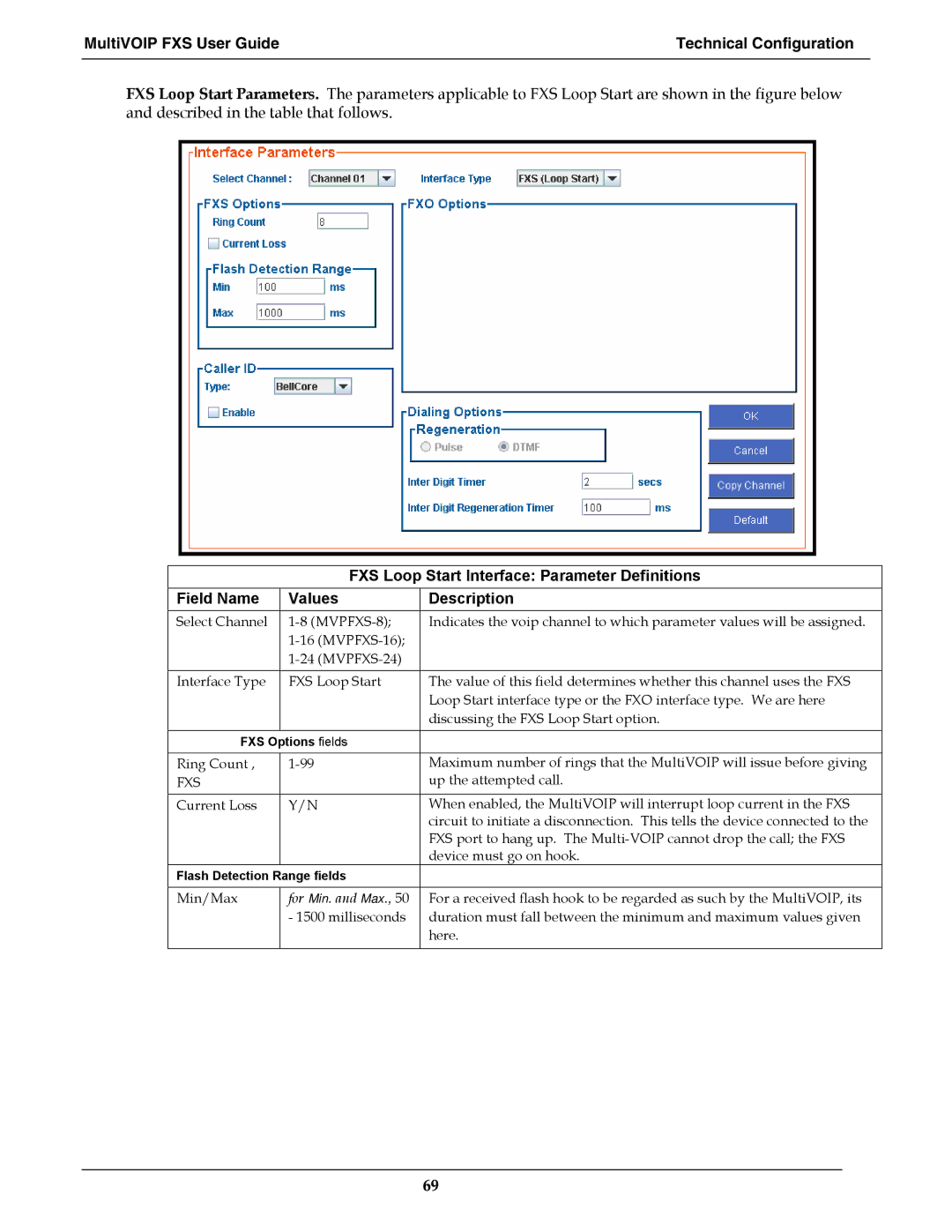
FXS Loop Start Parameters. The parameters applicable to FXS Loop Start are shown in the figure below and described in the table that follows.
FXS Loop Start Interface: Parameter Definitions
Field Name | Values | Description |
Select Channel | Indicates the voip channel to which parameter values will be assigned. | |
|
| |
|
| |
|
|
|
Interface Type | FXS Loop Start | The value of this field determines whether this channel uses the FXS |
|
| Loop Start interface type or the FXO interface type. We are here |
|
| discussing the FXS Loop Start option. |
|
|
|
FXS Options fields |
| |
|
|
|
Ring Count , | Maximum number of rings that the MultiVOIP will issue before giving | |
FXS |
| up the attempted call. |
|
|
|
Current Loss | Y/N | When enabled, the MultiVOIP will interrupt loop current in the FXS |
|
| circuit to initiate a disconnection. This tells the device connected to the |
|
| FXS port to hang up. The |
|
| device must go on hook. |
Flash Detection Range fields |
| |
|
|
|
Min/Max | for Min. and Max., 50 | For a received flash hook to be regarded as such by the MultiVOIP, its |
| - 1500 milliseconds | duration must fall between the minimum and maximum values given |
|
| here. |
|
|
|
69