NCT480 System Overview
NCT480 Series mini
Front View
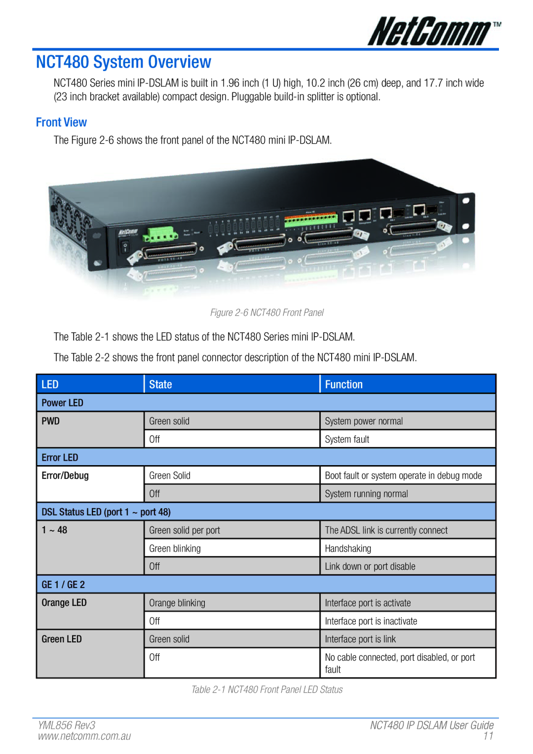
The Figure
Figure 2-6 NCT480 Front Panel
The Table
The Table
LED
State
Function
Power LED
PWD | Green solid | System power normal |
|
|
|
| Off | System fault |
|
|
|
Error LED |
|
|
|
|
|
Error/Debug | Green Solid | Boot fault or system operate in debug mode |
|
|
|
| Off | System running normal |
|
|
|
DSL Status LED (port 1 ~ port 48) |
| |
|
|
|
1 ~ 48 | Green solid per port | The ADSL link is currently connect |
|
|
|
| Green blinking | Handshaking |
|
|
|
| Off | Link down or port disable |
|
|
|
GE 1 / GE 2 |
|
|
|
|
|
Orange LED | Orange blinking | Interface port is activate |
|
|
|
| Off | Interface port is inactivate |
|
|
|
Green LED | Green solid | Interface port is link |
|
|
|
| Off | No cable connected, port disabled, or port |
|
| fault |
|
|
|
| Table | |
YML856 Rev3 | NCT480 IP DSLAM User Guide |
www.netcomm.com.au | 11 |