Ventilation
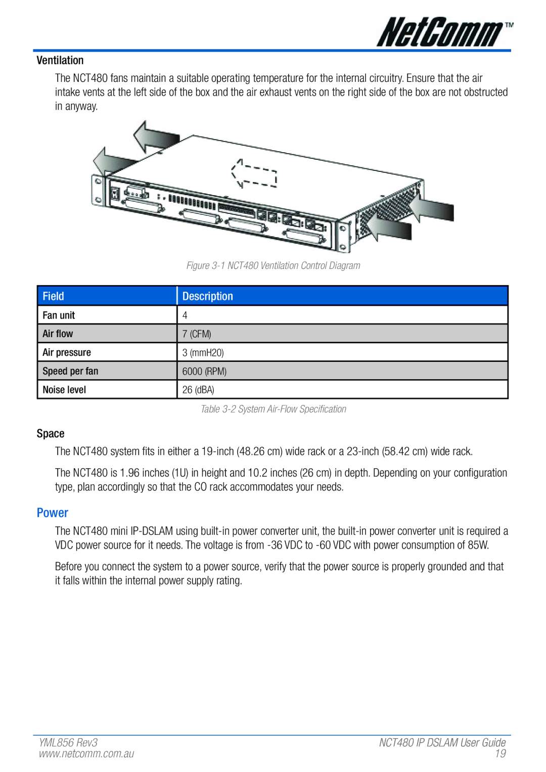
The NCT480 fans maintain a suitable operating temperature for the internal circuitry. Ensure that the air intake vents at the left side of the box and the air exhaust vents on the right side of the box are not obstructed in anyway.
Figure 3-1 NCT480 Ventilation Control Diagram
Field
Description
Fan unit | 4 |
|
|
|
|
Air flow | 7 | (CFM) |
|
|
|
Air pressure | 3 | (mmH20) |
|
| |
Speed per fan | 6000 (RPM) | |
|
| |
Noise level | 26 (dBA) | |
|
|
|
Table
Space
The NCT480 system fits in either a
The NCT480 is 1.96 inches (1U) in height and 10.2 inches (26 cm) in depth. Depending on your configuration type, plan accordingly so that the CO rack accommodates your needs.
Power
The NCT480 mini
Before you connect the system to a power source, verify that the power source is properly grounded and that it falls within the internal power supply rating.
YML856 Rev3 | NCT480 IP DSLAM User Guide |
www.netcomm.com.au | 19 |
