Appendix B System Connector Pin-Outs
NCT480 System connector
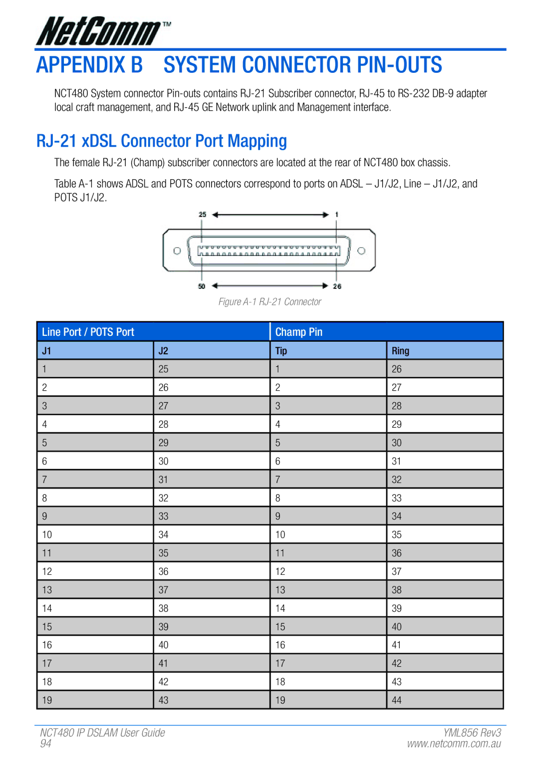
RJ-21 xDSL Connector Port Mapping
The female
Table
Figure A-1 RJ-21 Connector
Line Port / POTS Port
Champ Pin
J1
1
2
3
4
5
6
7
8
9
10
11
12
13
14
15
16
17
18
19
J2 | Tip | Ring |
25 | 1 | 26 |
26 | 2 | 27 |
27 | 3 | 28 |
28 | 4 | 29 |
29 | 5 | 30 |
30 | 6 | 31 |
31 | 7 | 32 |
32 | 8 | 33 |
33 | 9 | 34 |
34 | 10 | 35 |
35 | 11 | 36 |
36 | 12 | 37 |
37 | 13 | 38 |
38 | 14 | 39 |
39 | 15 | 40 |
40 | 16 | 41 |
41 | 17 | 42 |
42 | 18 | 43 |
43 | 19 | 44 |
|
|
|
NCT480 IP DSLAM User Guide | YML856 Rev3 |
94 | www.netcomm.com.au |