Making the Physical Connections
3.Connect the Ethernet cable to the Ethernet port on the router and the other end to your computer.
You should now have: the power adapter plugged in; the Ethernet cable connected between the router and your computer; and the DSL cable connected between the router and the DSL wall outlet.
Netopia 4553 Router status lights
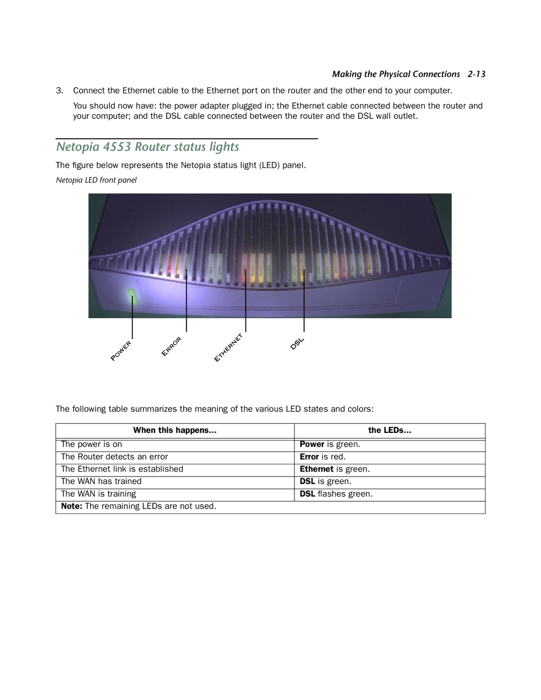
The figure below represents the Netopia status light (LED) panel.
Netopia LED front panel
P | OWER |
| ERROR |
| E | THERNET |
| DSL |
|
|
| ||||||
|
|
| ||||||
|
|
|
|
|
| |||
|
|
|
|
|
|
|
The following table summarizes the meaning of the various LED states and colors:
When this happens... | the LEDs... |
|
|
|
|
The power is on | Power is green. |
The Router detects an error | Error is red. |
|
|
The Ethernet link is established | Ethernet is green. |
|
|
The WAN has trained | DSL is green. |
|
|
The WAN is training | DSL flashes green. |
|
|
Note: The remaining LEDs are not used. |
|
|
|