ENGLISH

USER MANUAL

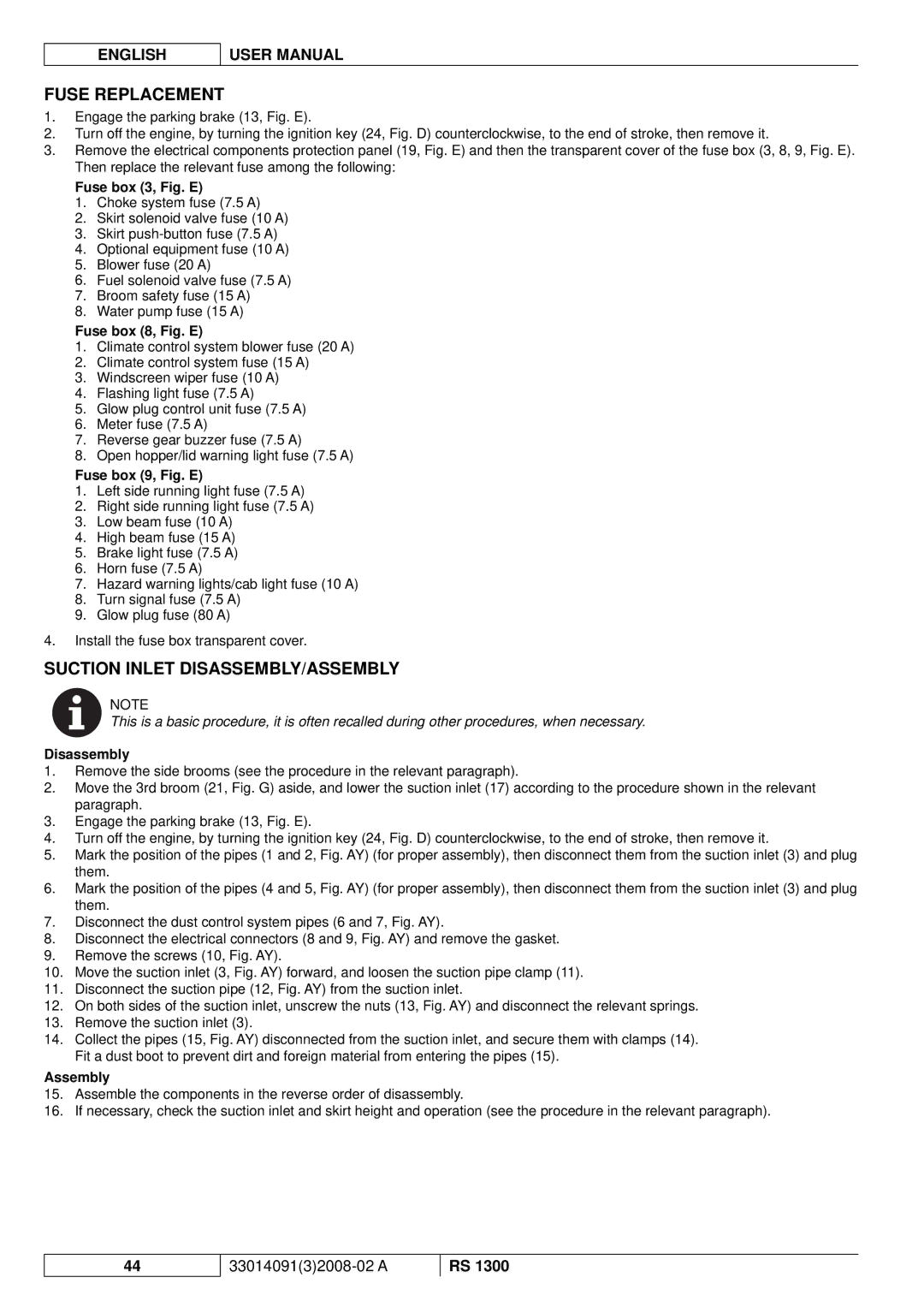
FUSE REPLACEMENT

1.Engage the parking brake (13, Fig. E).

2.Turn off the engine, by turning the ignition key (24, Fig. D) counterclockwise, to the end of stroke, then remove it.

3.Remove the electrical components protection panel (19, Fig. E) and then the transparent cover of the fuse box (3, 8, 9, Fig. E). Then replace the relevant fuse among the following:

Fuse box (3, Fig. E)

1.Choke system fuse (7.5 A)

2.Skirt solenoid valve fuse (10 A)

3.Skirt push-button fuse (7.5 A)

4.Optional equipment fuse (10 A)

5.Blower fuse (20 A)

6.Fuel solenoid valve fuse (7.5 A)

7.Broom safety fuse (15 A)

8.Water pump fuse (15 A)

Fuse box (8, Fig. E)

1.Climate control system blower fuse (20 A)

2.Climate control system fuse (15 A)

3.Windscreen wiper fuse (10 A)

4.Flashing light fuse (7.5 A)

5.Glow plug control unit fuse (7.5 A)

6.Meter fuse (7.5 A)

7.Reverse gear buzzer fuse (7.5 A)

8.Open hopper/lid warning light fuse (7.5 A)

Fuse box (9, Fig. E)

1.Left side running light fuse (7.5 A)

2.Right side running light fuse (7.5 A)

3.Low beam fuse (10 A)

4.High beam fuse (15 A)

5.Brake light fuse (7.5 A)

6.Horn fuse (7.5 A)

7.Hazard warning lights/cab light fuse (10 A)

8.Turn signal fuse (7.5 A)

9.Glow plug fuse (80 A)

4.Install the fuse box transparent cover.

SUCTION INLET DISASSEMBLY/ASSEMBLY

NOTE

This is a basic procedure, it is often recalled during other procedures, when necessary.

Disassembly

1.Remove the side brooms (see the procedure in the relevant paragraph).

2.Move the 3rd broom (21, Fig. G) aside, and lower the suction inlet (17) according to the procedure shown in the relevant paragraph.

3.Engage the parking brake (13, Fig. E).

4.Turn off the engine, by turning the ignition key (24, Fig. D) counterclockwise, to the end of stroke, then remove it.

5.Mark the position of the pipes (1 and 2, Fig. AY) (for proper assembly), then disconnect them from the suction inlet (3) and plug them.

6.Mark the position of the pipes (4 and 5, Fig. AY) (for proper assembly), then disconnect them from the suction inlet (3) and plug them.

7.Disconnect the dust control system pipes (6 and 7, Fig. AY).

8.Disconnect the electrical connectors (8 and 9, Fig. AY) and remove the gasket.

9.Remove the screws (10, Fig. AY).

10.Move the suction inlet (3, Fig. AY) forward, and loosen the suction pipe clamp (11).

11.Disconnect the suction pipe (12, Fig. AY) from the suction inlet.

12.On both sides of the suction inlet, unscrew the nuts (13, Fig. AY) and disconnect the relevant springs.

13.Remove the suction inlet (3).

14.Collect the pipes (15, Fig. AY) disconnected from the suction inlet, and secure them with clamps (14). Fit a dust boot to prevent dirt and foreign material from entering the pipes (15).

Assembly

15.Assemble the components in the reverse order of disassembly.

16.If necessary, check the suction inlet and skirt height and operation (see the procedure in the relevant paragraph).

44

33014091(3)2008-02 A

RS 1300

Page 166
Image 166
Nilfisk-ALTO RS 1300 manuel dutilisation Fuse Replacement, Suction Inlet DISASSEMBLY/ASSEMBLY, Disassembly, Assembly

RS 1300 specifications

Nilfisk-ALTO RS 1300 is a leading pressure washer renowned for its powerful performance and versatile applications. Designed for both commercial and residential use, this model caters to a wide range of cleaning needs, including patios, driveways, vehicles, and garden furniture.

One of the standout features of the RS 1300 is its robust motor, which delivers an impressive pressure of up to 130 bar. This high pressure allows users to tackle stubborn dirt and grime with ease. Coupled with a flow rate of up to 500 liters per hour, the machine ensures efficient cleaning in a shorter time frame.

The RS 1300 is equipped with a highly durable aluminum pump system that not only enhances the lifespan of the unit but also ensures consistent performance during heavy-duty cleaning tasks. The innovative design includes an adjustable pressure nozzle, which offers flexibility for various cleaning applications. Users can easily switch between different spray settings, allowing for tailored cleaning experiences.

In addition to its powerful performance, the Nilfisk-ALTO RS 1300 features a built-in detergent tank, making it convenient to use cleaning agents for enhanced results. This integration simplifies the cleaning process, as users can apply soap directly through the spray gun, boosting efficiency when dealing with tough stains.

Safety and ease of use are paramount in the design of the RS 1300. The machine comes with a safety lock feature to prevent accidental starts, providing peace of mind during storage and transport. Its ergonomic design ensures a comfortable grip, reducing user fatigue during prolonged use.

The RS 1300 is easy to transport, thanks to its lightweight design and integrated wheels. Users can effortlessly maneuver the unit around their property or job site. Additionally, storage is made simple with practical onboard storage solutions for the hose and accessories.

Overall, the Nilfisk-ALTO RS 1300 stands out for its combination of power, convenience, and user-friendly features. With its advanced technology and robust construction, it is a reliable choice for anyone seeking a high-performance pressure washer to tackle their cleaning challenges effectively. Whether for professional or home use, the RS 1300 is designed to meet the rigorous demands of various cleaning applications.