2 – 16
1 | 2 | 3 | 2 | 6 |
31 5 or 8 | ||||
|
|
|
| 7 |
|
| bit0 | bit7 |
| |
|
| OPTXD | Command (first) | Command (second) | |
|
|
| |||
Power ON |
| OPCLK |
|
| |
|
|
|
| ||
|
| bit0 |
| bit7 | |
Write instruction for LSI | 1 | OPRXD |
| Command response (second) | |
reset | Command response (first) | ||||
| |||||
|
|
|
| ||
|
|
| Note |
| |
|
|
|
|
| |
LSI write for LED data, | 2 |
|
|
| |
etc. |
|
|
| ||
|
|
|
| ||
Read instruction for | 3 | Reset |
|
| |
within |
|
| |||
data read |
|
| |||
|
|
| |||
| BU5148S |
|
| ||
|
|
|
| ||
| 4 |
|
|
| |
Response check | NO |
|
|
| |
|
|
|
| ||
for OK or NG |
|
|
|
| |
YES |
|
|
|
| |
| Error notification | 7 |
|
| |
5 |
|
|
|
| |
| Instruction for | 8 |
|
| |
6 | retransmission |
|
| ||
|
|
| |||
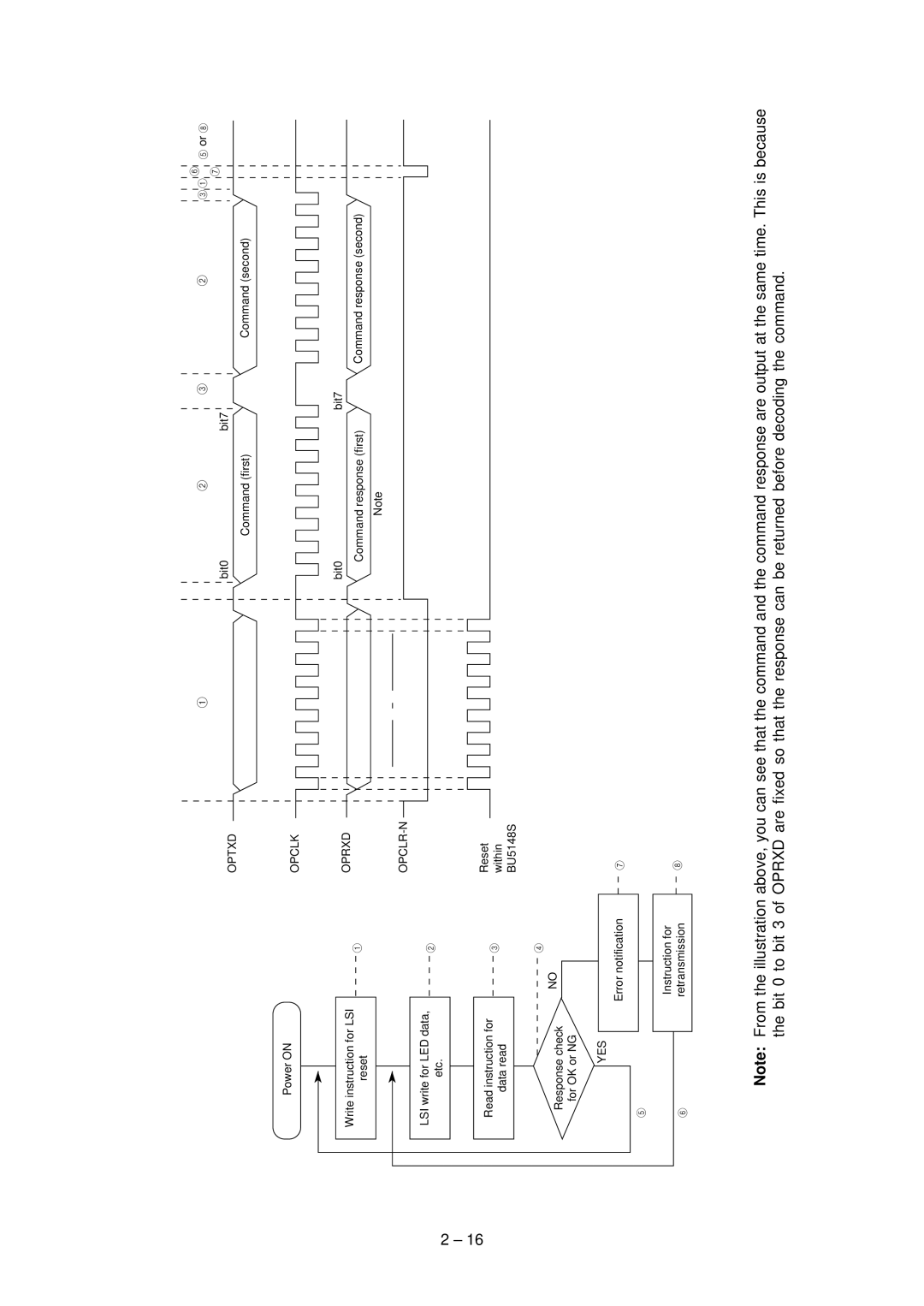
Note: From the illustration above, you can see that the command and the command response are output at the same time. This is because the bit 0 to bit 3 of OPRXD are fixed so that the response can be returned before decoding the command.