3.3.5Gear Case Assy
(1)Remove the printhead (see 3.31).
(2)Remove the upper cover (see 3.3.4 (1) – (5)).
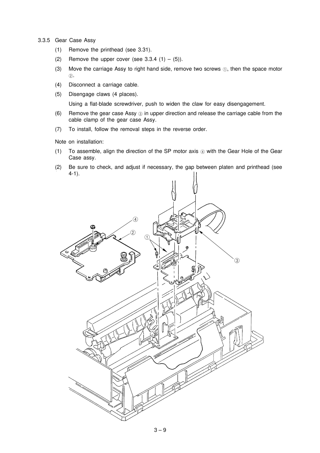
(3)Move the carriage Assy to right hand side, remove two screws 1, then the space motor
2.
(4)Disconnect a carriage cable.
(5)Disengage claws (4 places).
Using a
(6)Remove the gear case Assy 3 in upper direction and release the carriage cable from the cable clamp of the gear case Assy.
(7)To install, follow the removal steps in the reverse order.
Note on installation:
(1)To assemble, align the direction of the SP motor axis 4 with the Gear Hole of the Gear Case assy.
(2)Be sure to check, and adjust if necessary, the gap between platen and printhead (see
4
2
1
3
3 – 9