No. | Item |
| Specification |
between | the | 1±0.5 | |
platen | and the | paper |
|
pan |
|
|
|
|
|
|
|
Rear
Drawing | Adjustment method | |
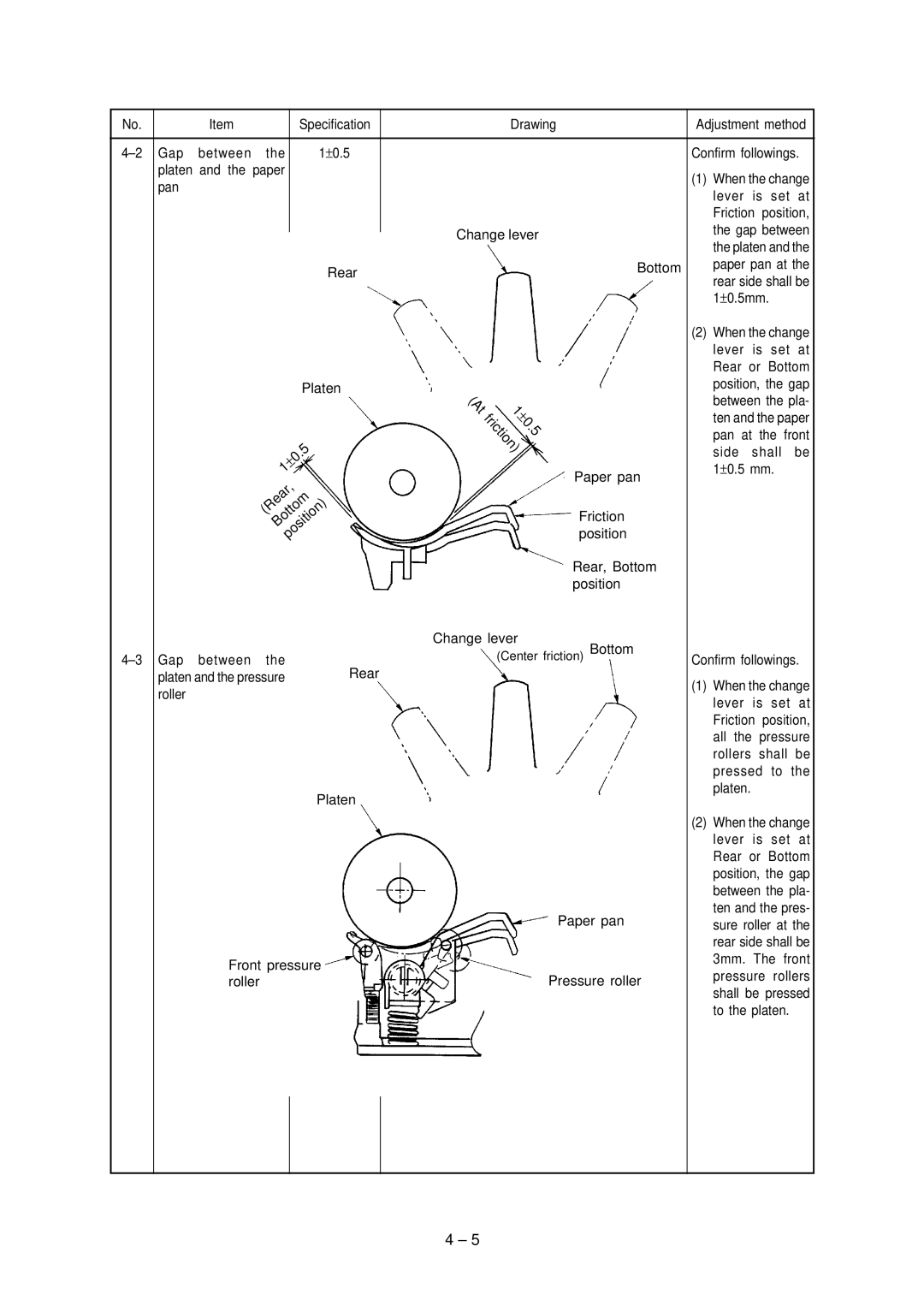
| Confirm followings. | |
| (1) When the change | |
| lever is set at | |
| Friction position, | |
Change lever | the gap between | |
the platen and the | ||
| ||
Bottom | paper pan at the | |
| rear side shall be | |
| 1±0.5mm. |
Platen
|
| .5 |
| 0 | |
± |
| |
1 |
|
|
(Rear, |
| |
(At | 1 |
|
| ± | |
| 0 | |
friction) | . | |
|
| 5 |
Paper pan
(2)When the change lever is set at Rear or Bottom position, the gap between the pla- ten and the paper pan at the front
side shall be 1±0.5 mm.
Bottom |
position) |
Rear | |
platen and the pressure | |
roller |
|
Platen
Front pressure roller
Friction position
Rear, Bottom position
Change lever
(Center friction) Bottom
Paper pan
Pressure roller
Confirm followings.
(1)When the change lever is set at Friction position, all the pressure rollers shall be pressed to the platen.
(2)When the change lever is set at Rear or Bottom position, the gap between the pla- ten and the pres- sure roller at the rear side shall be 3mm. The front pressure rollers shall be pressed to the platen.
4 – 5
