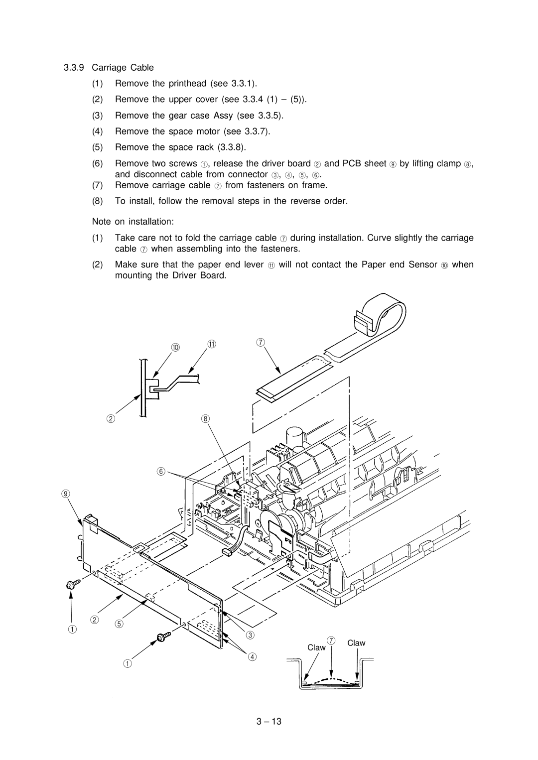
3.3.9Carriage Cable
(1)Remove the printhead (see 3.3.1).
(2)Remove the upper cover (see 3.3.4 (1) – (5)).
(3)Remove the gear case Assy (see 3.3.5).
(4)Remove the space motor (see 3.3.7).
(5)Remove the space rack (3.3.8).
(6)Remove two screws 1, release the driver board 2 and PCB sheet 9 by lifting clamp 8, and disconnect cable from connector 3, 4, 5, 6.
(7)Remove carriage cable 7 from fasteners on frame.
(8)To install, follow the removal steps in the reverse order.
Note on installation:
(1)Take care not to fold the carriage cable 7 during installation. Curve slightly the carriage cable 7 when assembling into the fasteners.
(2)Make sure that the paper end lever A will not contact the Paper end Sensor 0 when mounting the Driver Board.
0 A 7
2 8
6
9
![]() 2 5 1
2 5 1
3
Claw
4
7 Claw
1
3 – 13