3.3.7Space Motor, Guide Roller Assy
(1)Remove the printhead (see 3.3.1).
(2)Remove the upper cover (see 3.3.4 (1) – (5)).
(3)Remove the gear case Assy (see 3.3.5).
(4)Remove the PC connector (see 3.3.6).
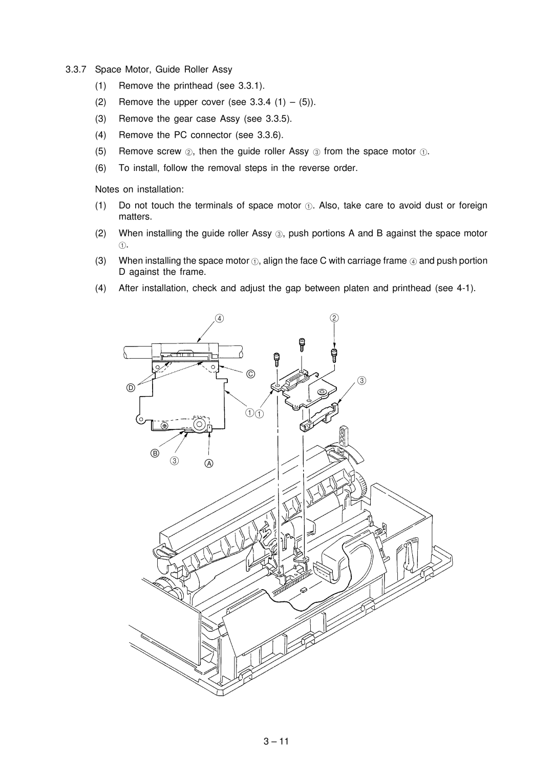
(5)Remove screw 2, then the guide roller Assy 3 from the space motor 1.
(6)To install, follow the removal steps in the reverse order.
Notes on installation:
(1)Do not touch the terminals of space motor 1. Also, take care to avoid dust or foreign matters.
(2)When installing the guide roller Assy 3, push portions A and B against the space motor
1.
(3)When installing the space motor 1, align the face C with carriage frame 4 and push portion D against the frame.
(4)After installation, check and adjust the gap between platen and printhead (see
42
C
3
D
11
B
3A
3 – 11