3.3.14Operation Panel PCB (LEOP)
(1)Remove the upper cover (see 3.3.4 (1) – (5)).
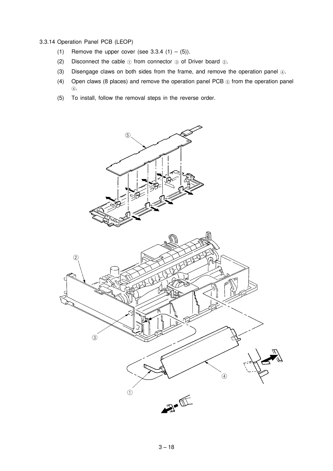
(2)Disconnect the cable 1 from connector 3 of Driver board 2.
(3)Disengage claws on both sides from the frame, and remove the operation panel 4.
(4)Open claws (8 places) and remove the operation panel PCB 5 from the operation panel
4.
(5)To install, follow the removal steps in the reverse order.
5
2
3
4
1
3 – 18