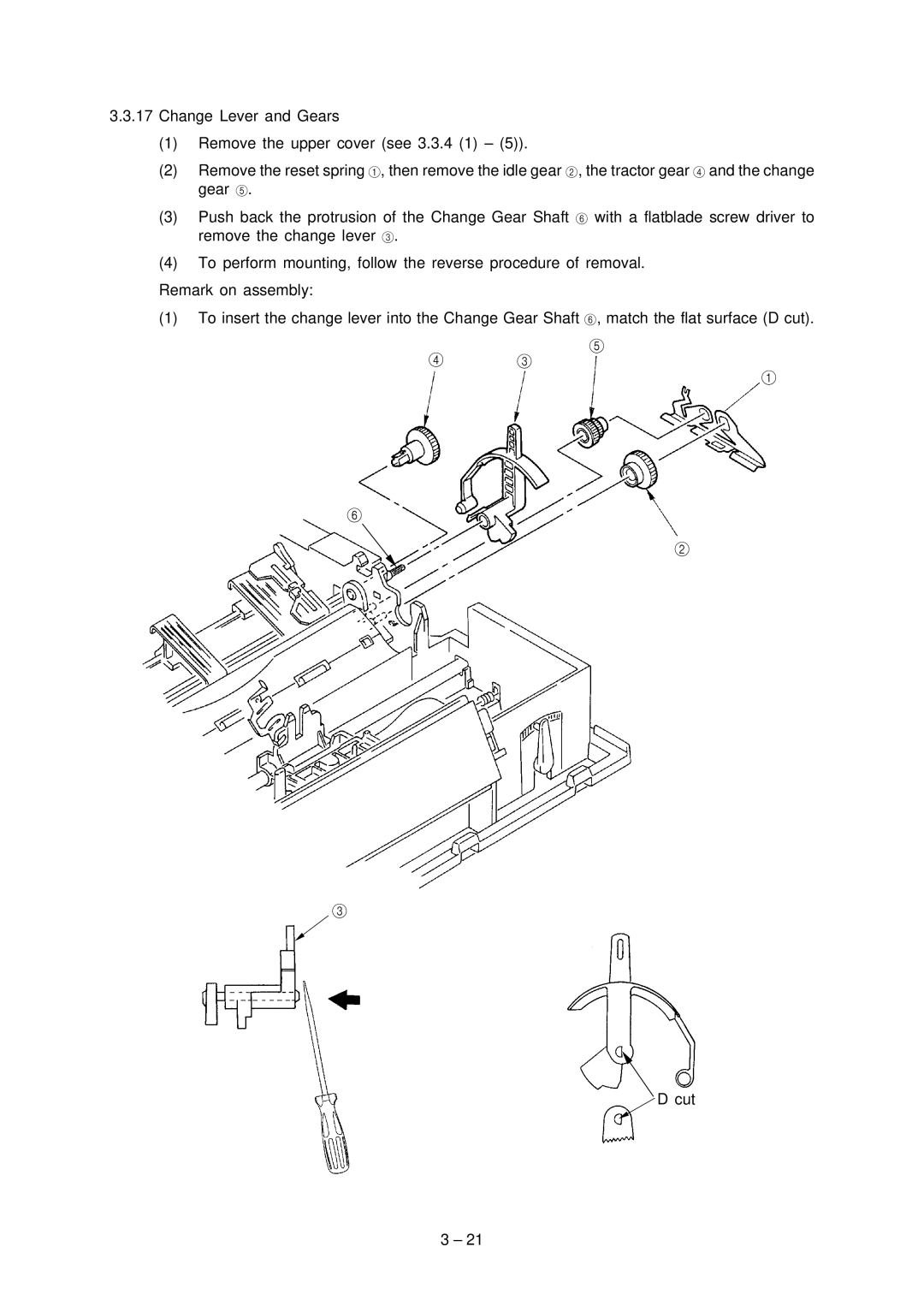
3.3.17Change Lever and Gears
(1)Remove the upper cover (see 3.3.4 (1) – (5)).
(2)Remove the reset spring 1, then remove the idle gear 2, the tractor gear 4 and the change gear 5.
(3)Push back the protrusion of the Change Gear Shaft 6 with a flatblade screw driver to remove the change lever 3.
(4)To perform mounting, follow the reverse procedure of removal.
Remark on assembly:
(1)To insert the change lever into the Change Gear Shaft 6, match the flat surface (D cut).
5
4 3
1
6
2
3
![]() D cut
D cut
3 – 21