3.3.1Printhead
(1)Open the access over.
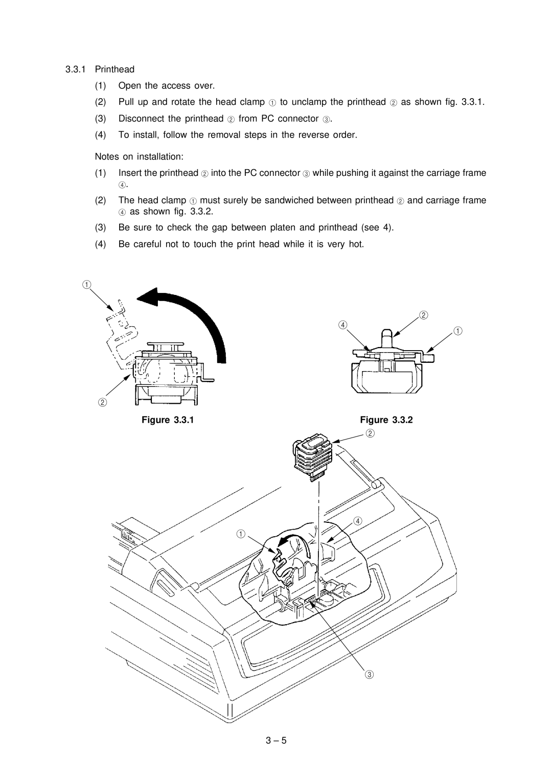
(2)Pull up and rotate the head clamp 1 to unclamp the printhead 2 as shown fig. 3.3.1.
(3)Disconnect the printhead 2 from PC connector 3.
(4)To install, follow the removal steps in the reverse order.
Notes on installation:
(1)Insert the printhead 2 into the PC connector 3 while pushing it against the carriage frame
4.
(2)The head clamp 1 must surely be sandwiched between printhead 2 and carriage frame 4 as shown fig. 3.3.2.
(3)Be sure to check the gap between platen and printhead (see 4).
(4)Be careful not to touch the print head while it is very hot.
1
2
4
2
1
Figure 3.3.1 | Figure 3.3.2 |
| 2 |
4
1
3
3 – 5