7.5 BADR3
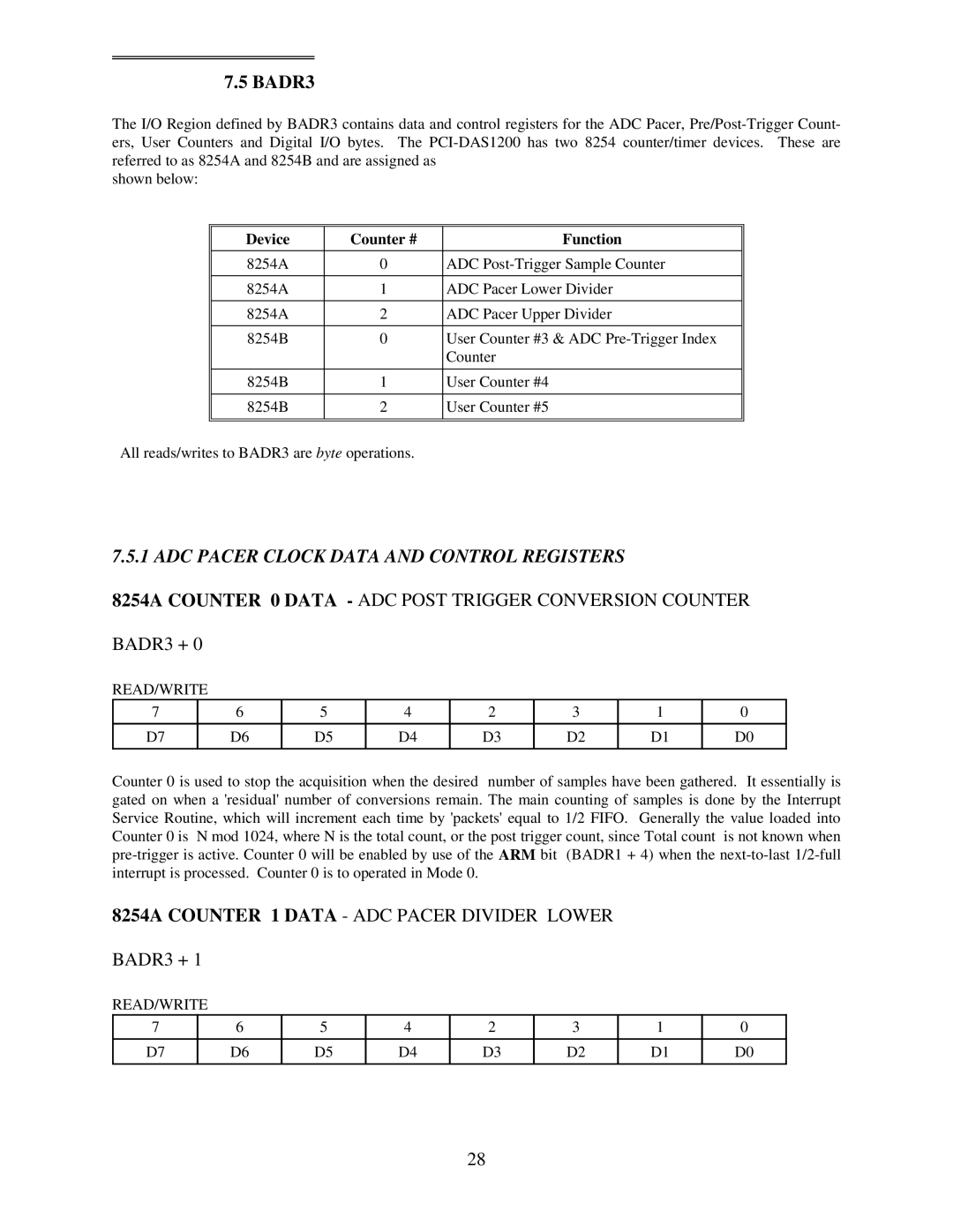
The I/O Region defined by BADR3 contains data and control registers for the ADC Pacer,
shown below:
Device | Counter # | Function |
|
|
|
8254A | 0 | ADC |
|
|
|
8254A | 1 | ADC Pacer Lower Divider |
|
|
|
8254A | 2 | ADC Pacer Upper Divider |
|
|
|
8254B | 0 | User Counter #3 & ADC |
|
| Counter |
|
|
|
8254B | 1 | User Counter #4 |
|
|
|
8254B | 2 | User Counter #5 |
|
|
|
|
|
|
All reads/writes to BADR3 are byte operations.
7.5.1 ADC PACER CLOCK DATA AND CONTROL REGISTERS
8254A COUNTER 0 DATA - ADC POST TRIGGER CONVERSION COUNTER
BADR3 + 0
READ/WRITE
7 | 6 | 5 | 4 | 2 | 3 | 1 | 0 |
|
|
|
|
|
|
|
|
D7 | D6 | D5 | D4 | D3 | D2 | D1 | D0 |
|
|
|
|
|
|
|
|
Counter 0 is used to stop the acquisition when the desired number of samples have been gathered. It essentially is gated on when a 'residual' number of conversions remain. The main counting of samples is done by the Interrupt Service Routine, which will increment each time by 'packets' equal to 1/2 FIFO. Generally the value loaded into Counter 0 is N mod 1024, where N is the total count, or the post trigger count, since Total count is not known when
8254A COUNTER 1 DATA - ADC PACER DIVIDER LOWER
BADR3 + 1
READ/WRITE
7 | 6 | 5 | 4 | 2 | 3 | 1 | 0 |
|
|
|
|
|
|
|
|
D7 | D6 | D5 | D4 | D3 | D2 | D1 | D0 |
|
|
|
|
|
|
|
|
28