Chapter 2 Parts and their functions
2-5 Time code related section
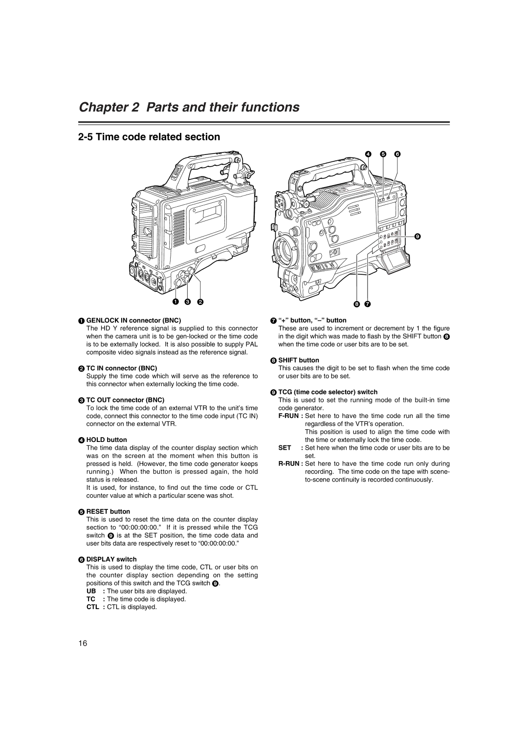
4 5 6
9
1 3 2
1 GENLOCK IN connector (BNC)
The HD Y reference signal is supplied to this connector when the camera unit is to be
2 TC IN connector (BNC)
Supply the time code which will serve as the reference to this connector when externally locking the time code.
3 TC OUT connector (BNC)
To lock the time code of an external VTR to the unit’s time code, connect this connector to the time code input (TC IN) connector on the external VTR.
4 HOLD button
The time data display of the counter display section which was on the screen at the moment when this button is pressed is held. (However, the time code generator keeps running.) When the button is pressed again, the hold status is released.
It is used, for instance, to find out the time code or CTL counter value at which a particular scene was shot.
5 RESET button
This is used to reset the time data on the counter display section to “00:00:00:00.” If it is pressed while the TCG switch 9 is at the SET position, the time code data and user bits data are respectively reset to “00:00:00:00.”
6 DISPLAY switch
This is used to display the time code, CTL or user bits on the counter display section depending on the setting positions of this switch and the TCG switch 9.
UB | : The user bits are displayed. |
TC | : The time code is displayed. |
CTL | : CTL is displayed. |
8 7
7 “+” button, “–” button
These are used to increment or decrement by 1 the figure in the digit which was made to flash by the SHIFT button 8 when the time code or user bits are to be set.
8 SHIFT button
This causes the digit to be set to flash when the time code or user bits are to be set.
9 TCG (time code selector) switch
This is used to set the running mode of the
This position is used to align the time code with the time or externally lock the time code.
SET : Set here when the time code or user bits are to be set.
16