Chapter 4 Adjustments and settings for recording
4-5 Setting the time data
The time code setting range extends from 00:00:00:00 to 23:59:59:29.
4-5-1 Setting the user bits
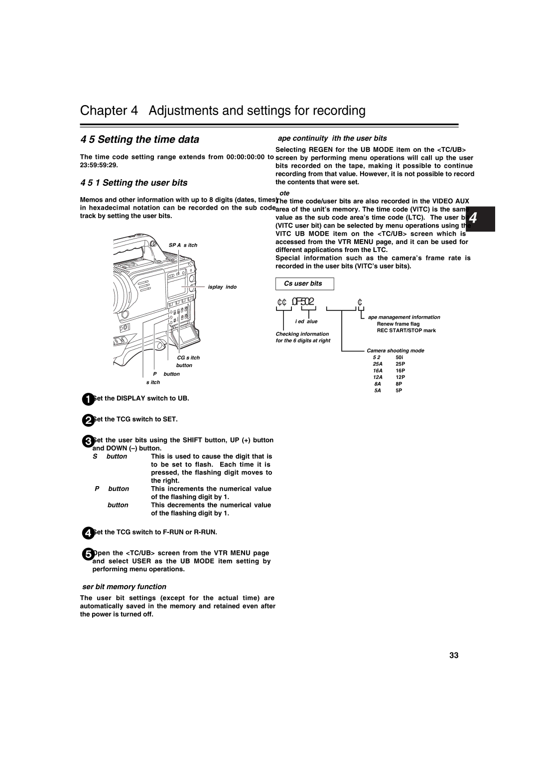
Memos and other information with up to 8 digits (dates, times) in hexadecimal notation can be recorded on the sub code track by setting the user bits.
DISPLAY switch
![]() Display window
Display window
TCG switch
DOWN
UP (+) button
HOLD switch
1 Set the DISPLAY switch to UB.
2 Set the TCG switch to SET.
3 Set the user bits using the SHIFT button, UP (+) button and DOWN
SHIFT button: This is used to cause the digit that is to be set to flash. Each time it is pressed, the flashing digit moves to the right.
UP (+) button: This increments the numerical value of the flashing digit by 1.
DOWN
4 Set the TCG switch to
5 Open the <TC/UB> screen from the VTR MENU page and select USER as the UB MODE item setting by performing menu operations.
User bit memory function
The user bit settings (except for the actual time) are automatically saved in the memory and retained even after the power is turned off.
Tape continuity with the user bits
Selecting REGEN for the UB MODE item on the <TC/UB> screen by performing menu operations will call up the user bits recorded on the tape, making it possible to continue recording from that value. However, it is not possible to record the contents that were set.
<Note>
The time code/user bits are also recorded in the VIDEO AUX area of the unit’s memory. The time code (VITC) is the same value as the sub code area’s time code (LTC). The user bit 4 (VITC user bit) can be selected by menu operations using the VITC UB MODE item on the <TC/UB> screen which is accessed from the VTR MENU page, and it can be used for different applications from the LTC.
Special information such as the camera’s frame rate is recorded in the user bits (VITC’s user bits).
VITC’s user bits
¢¢:0F:50:2¢
|
|
|
|
|
|
|
|
|
|
| Tape management information | ||
|
|
|
|
|
|
|
|
|
|
| |||
|
| Fixed value |
|
|
|
| ≥ Renew frame flag | ||||||
|
|
|
|
|
|
|
|
|
|
| |||
|
|
|
|
|
|
|
|
|
|
| ≥ REC START/STOP mark | ||
Checking information | |||||||||||||
|
|
|
|
|
| ||||||||
for the 6 digits at right. |
|
|
|
|
|
| |||||||
|
|
|
|
|
|
|
|
|
|
| Camera shooting mode | ||
|
|
|
|
|
|
|
|
|
|
| |||
|
|
|
|
|
|
| 502: | 50i | |||||
|
|
|
|
|
|
|
|
|
|
| 25A: | 25P | |
|
|
|
|
|
|
|
|
|
|
| 16A: | 16P | |
|
|
|
|
|
|
|
|
|
|
| 12A: | 12P | |
|
|
|
|
|
|
|
|
|
|
| 08A: | 8P | |
|
|
|
|
|
|
|
|
|
|
| 05A: | 5P | |
33
