Chapter 4 Adjustments and settings for recording
4-8 Menu-driven function setup
The functions can be set up using the unit’s menus.
4-8-1 Setting the USER SW GAIN switching
This unit allows three other modes to be used in addition to the L/M/H standard gain settings: the analog
To select these functions, perform menu operations to open the <USER SW GAIN> screen from the OPERATION page, select the S.GAIN item and DS.GAIN item, and preset the gain to be used for each item. Furthermore, select the LINE MIX function on the <USER SW> screen.
For instance, if the S.GAIN, DS.GAIN and LINE MIX GAIN functions have been allocated to the USER MAIN button, USER1 button or USER2 button, the gain can be increased by using these buttons in combination with the USER buttons.
1)To increase the gain without increasing the perceptible noise
Combine the DS.GAIN or LINE MIX GAIN function with the L/M/H gain.
2)To increase the normal analog gain (in which case, the amount of noise will increase)
Use only the S.GAIN function.
<Note>
Since the amount of noise will increase when the gain is increased in this way, bear in mind that the AUTO IRIS accuracy will be adversely affected.
3)To use the unit in the ultra-high-sensitivity mode
Use the S.GAIN function and DS.GAIN or LINE MIX GAIN function in combination. However, exercise care during operation since image lag will become more conspicuous with moving subjects the more the gain is increased by using the DS.GAIN function.
When shooting moving subjects, keep the gain increase with the LINE MIX GAIN function or DS.GAIN function to under +12 dB.
#< USER SW GAIN >
S.GAIN ¢30dB ¢36dB ¢42dB ¢48dB
DS.GAIN
¢6dB f (25P) ¢12dB f (16P) ¢12dB f (12P) ¢12dB f (8P) ¢20dB f (5P)
Setting items and details
S.GAIN: An analog gain increase with an asterisk is one that is valid. One without an asterisk is invalid.
DS.GAIN: A cumulative gain increase with an asterisk is one that is valid. One without an asterisk is invalid.
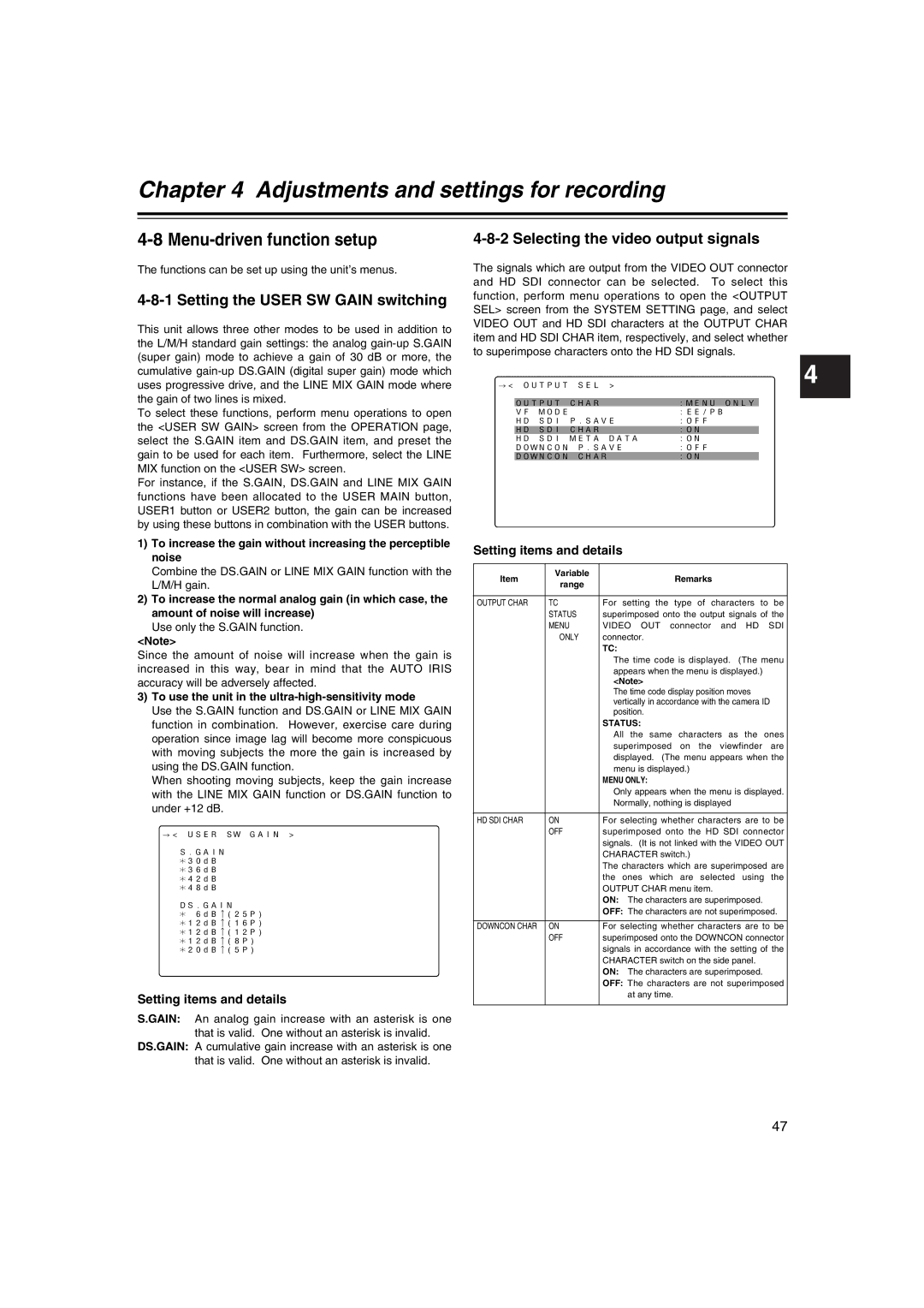
4-8-2 Selecting the video output signals
The signals which are output from the VIDEO OUT connector and HD SDI connector can be selected. To select this function, perform menu operations to open the <OUTPUT SEL> screen from the SYSTEM SETTING page, and select VIDEO OUT and HD SDI characters at the OUTPUT CHAR item and HD SDI CHAR item, respectively, and select whether to superimpose characters onto the HD SDI signals.
#< OUTPUT SEL > | 4 | ||
|
| ||
| OUTPUT CHAR | :MENU ONLY |
|
VF MODE | :EE/PB | ||
HD SDI P.SAVE | :OFF | ||
| HD SDI CHAR | :ON |
|
| HD SDI META DATA | :ON |
|
DOWNCON P.SAVE | :OFF | ||
| DOWNCON CHAR | :ON |
|
Setting items and details
Item | Variable | Remarks | |
range | |||
|
| ||
|
|
| |
OUTPUT CHAR | TC | For setting the type of characters to be | |
| STATUS | superimposed onto the output signals of the | |
| MENU | VIDEO OUT connector and HD SDI | |
| ONLY | connector. | |
|
| TC: | |
|
| The time code is displayed. (The menu | |
|
| appears when the menu is displayed.) | |
|
| <Note> | |
|
| The time code display position moves | |
|
| vertically in accordance with the camera ID | |
|
| position. | |
|
| STATUS: | |
|
| All the same characters as the ones | |
|
| superimposed on the viewfinder are | |
|
| displayed. (The menu appears when the | |
|
| menu is displayed.) | |
|
| MENU ONLY: | |
|
| Only appears when the menu is displayed. | |
|
| Normally, nothing is displayed | |
|
|
| |
HD SDI CHAR | ON | For selecting whether characters are to be | |
| OFF | superimposed onto the HD SDI connector | |
|
| signals. (It is not linked with the VIDEO OUT | |
|
| CHARACTER switch.) | |
|
| The characters which are superimposed are | |
|
| the ones which are selected using the | |
|
| OUTPUT CHAR menu item. | |
|
| ON: The characters are superimposed. | |
|
| OFF: The characters are not superimposed. | |
|
|
| |
DOWNCON CHAR | ON | For selecting whether characters are to be | |
| OFF | superimposed onto the DOWNCON connector | |
|
| signals in accordance with the setting of the | |
|
| CHARACTER switch on the side panel. | |
|
| ON: The characters are superimposed. | |
|
| OFF: The characters are not superimposed | |
|
| at any time. | |
|
|
|
47