Chapter 7 Menu description tables
7-4-1 VF DISPLAYS
Item/ |
|
| Variable |
|
| Remarks |
Data storage | range |
|
| |||
|
|
| ||||
|
|
|
| |||
DISP CONDITION |
| NORMAL | NORMAL: The statuses are displayed at all | |||
|
|
| HOLD |
|
| times. |
|
|
|
| HOLD: | The statuses are displayed only | |
|
|
|
|
|
| when the MODE CHECK switch is |
C U | F | E |
|
|
| pressed. |
|
|
|
|
| ||
DISP MODE |
|
| 1 | For performing the DISP MODE setting. This | ||
|
|
| 2 | item is used to select the camera’s warning or | ||
|
|
| 3 | message displays. For details, refer to | ||
|
|
|
| Display modes and setting changes/ | ||
C U | F | E |
| adjustment result messages.” | ||
|
|
|
| |||
DS.GAIN DISP |
| GAIN | For selecting whether to display the DS.GAIN | |||
|
|
| FRM RATE | value as a frame rate value (P) or gain value | ||
|
|
|
| (:). |
|
|
|
|
|
| GAIN: |
| The DS.GAIN value is displayed |
|
|
|
|
|
| as a gain value (:). |
|
|
|
| FRM RATE: The DS.GAIN value is displayed | ||
C U | F | E |
|
|
| as a frame rate value (P). |
VF OUT |
|
| Y | For selecting the VF output. | ||
|
|
| NAM | Y: | Luminance signal | |
RNAM: The signal with the highest level among
|
| G |
| the R, G and B signals is output. |
|
| B | R: | R channel signal |
|
|
| G: | G channel signal |
C U | F | E | B: | B channel signal |
|
|
|
| |
VF DTL |
| 0 | For performing the VF DTL selection. This | |
|
| : | item is used to further emphasize the DTL of | |
|
| 2 | ||
|
| the VF signals. If 0 is set, the DTL will be the | ||
|
| : | ||
C U F E 5 | same as that of the main line signals. | |||
ZEBRA1 DETECT | 0% | For setting the ZEBRA1 detection level (IRE | ||
|
| : | level). |
|
|
| 70% |
| |
|
|
|
| |
|
| : |
|
|
C U | F | E 109% |
|
|
7-4-2 VF MARKER
Item/ |
| Variable | Remarks |
Data storage |
| range | |
|
| ||
TABLE | A |
| For selecting the VF MARKER setting table. |
BThis item is used to set the current values of
|
| table A or B which have been selected using | |
C U F | E | the menu items listed below. | |
|
|
| |
CENTER MARK | OFF | For selecting the center marker. | |
| 1 | OFF: The center marker is not displayed. | |
| 2 | 1: | + (large) |
| 3 | 2: | Center blank (large) |
| 4 | 3: | + (small) |
C U F | E | 4: | Center blank (small) |
|
|
| |
SAFETY ZONE | OFF | For selecting the type of safety zone frame. | |
1OFF: The safety zone frame is not displayed.
| 2 | 1: | Box |
C U F | E | 2: | Corner frames |
|
|
| |
SAFETY AREA | 80% | For setting the position of the safety zone. | |
| : |
|
|
| 90% |
|
|
| : |
|
|
C U F E 100% |
|
| |
FRAME SIG | 4:3 | For setting the frame marker. | |
| 13:9 | The VISTA setting is 16:8.65. | |
| 14:9 |
|
|
C U F E VISTA |
|
| |
FRAME MARK | ON | For selecting ON or OFF for the frame | |
C U F E OFF | marker. | ||
FRAME LVL | 00 | For setting the level outside the frame marker. | |
| : | 0: Equivalent to signal OFF | |
| 15 | ||
| 15: Same brightness as center area | ||
|
| ||
|
|
| However, this setting has no effect if |
C U F | E |
| FRAME SIG is set to VISTA. |
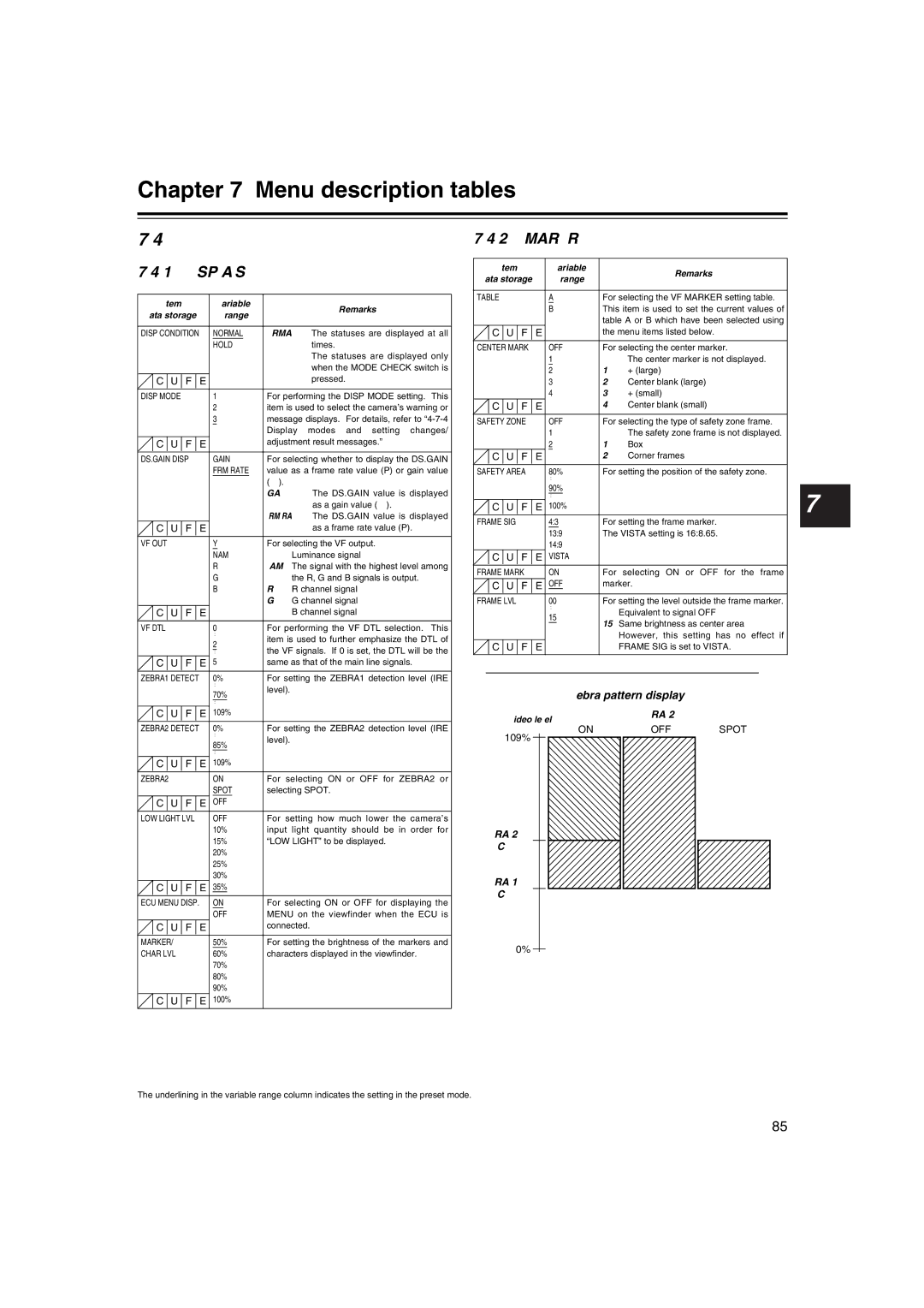
Zebra pattern display
Video level | ZEBRA 2 |
|
7
ZEBRA2 DETECT | 0% | For setting the ZEBRA2 detection level (IRE |
| : | level). |
| 85% | |
|
| |
| : |
|
C U F E 109% |
| |
ZEBRA2 | ON | For selecting ON or OFF for ZEBRA2 or |
| SPOT | selecting SPOT. |
C U F E OFF |
| |
LOW LIGHT LVL | OFF | For setting how much lower the camera’s |
| 10% | input light quantity should be in order for |
| 15% | “LOW LIGHT” to be displayed. |
| 20% |
|
| 25% |
|
| 30% |
|
C U F E 35% |
| |
ECU MENU DISP. | ON | For selecting ON or OFF for displaying the |
| OFF | MENU on the viewfinder when the ECU is |
C U F | E | connected. |
|
|
|
MARKER/ | 50% | For setting the brightness of the markers and |
ON
109%
ZEBRA 2
DETECT
ZEBRA 1
DETECT
OFFSPOT
CHAR LVL | 60% | characters displayed in the viewfinder. |
| 70% |
|
| 80% |
|
| 90% |
|
C U F | E 100% |
|
0%
The underlining in the variable range column indicates the setting in the preset mode.
85