Chapter 4 Adjustments and settings for recording
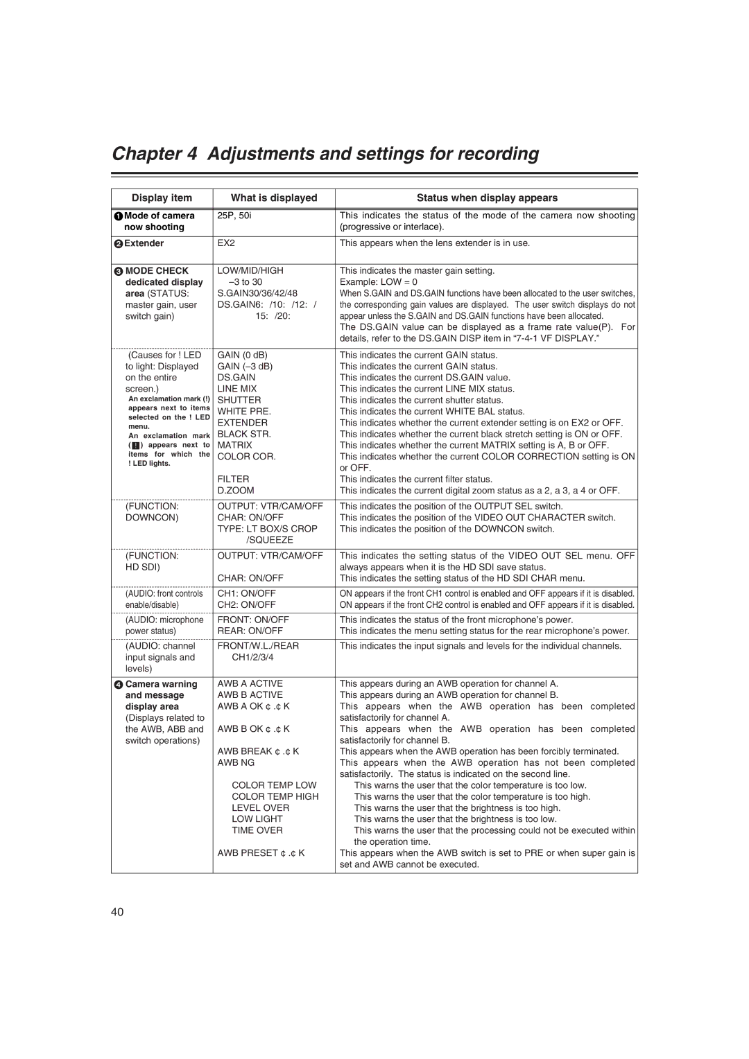
Display item | What is displayed | Status when display appears | |||||
|
|
|
|
|
|
| |
|
|
|
|
|
|
| |
1Mode of camera | 25P, 50i | This indicates the status of the mode of the camera now shooting | |||||
now shooting |
| (progressive or interlace). | |||||
|
|
| |||||
2Extender | EX2 | This appears when the lens extender is in use. | |||||
|
|
|
|
|
|
| |
3 MODE CHECK | LOW/MID/HIGH | This indicates the master gain setting. | |||||
dedicated display | Example: LOW = 0 | ||||||
area (STATUS: | S.GAIN30/36/42/48 | When S.GAIN and DS.GAIN functions have been allocated to the user switches, | |||||
master gain, user | DS.GAIN6:/10:/12:/ | the corresponding gain values are displayed. The user switch displays do not | |||||
switch gain) | 15:/20: | appear unless the S.GAIN and DS.GAIN functions have been allocated. | |||||
|
|
|
|
|
| The DS.GAIN value can be displayed as a frame rate value(P). For | |
|
|
|
|
|
| details, refer to the DS.GAIN DISP item in | |
|
|
|
|
|
|
| |
(Causes for ! LED | GAIN (0 dB) | This indicates the current GAIN status. | |||||
to light: Displayed | GAIN | This indicates the current GAIN status. | |||||
on the entire | DS.GAIN | This indicates the current DS.GAIN value. | |||||
screen.) | LINE MIX | This indicates the current LINE MIX status. | |||||
≥ An exclamation mark (!) | SHUTTER | This indicates the current shutter status. | |||||
appears next to items | WHITE PRE. | This indicates the current WHITE BAL status. | |||||
selected on the ! LED | |||||||
EXTENDER | This indicates whether the current extender setting is on EX2 or OFF. | ||||||
menu. | |||||||
BLACK STR. | This indicates whether the current black stretch setting is ON or OFF. | ||||||
≥ An exclamation mark | |||||||
( |
| ) appears next to | MATRIX | This indicates whether the current MATRIX setting is A, B or OFF. | |||
! | |||||||
items for which the | COLOR COR. | This indicates whether the current COLOR CORRECTION setting is ON | |||||
! LED lights. |
| or OFF. | |||||
|
|
|
|
|
| ||
|
|
|
|
| FILTER | This indicates the current filter status. | |
|
|
|
|
| D.ZOOM | This indicates the current digital zoom status as a2, a3, a4 or OFF. | |
|
|
|
|
|
| ||
(FUNCTION: | OUTPUT: VTR/CAM/OFF | This indicates the position of the OUTPUT SEL switch. | |||||
DOWNCON) | CHAR: ON/OFF | This indicates the position of the VIDEO OUT CHARACTER switch. | |||||
|
|
|
|
| TYPE: LT BOX/S CROP | This indicates the position of the DOWNCON switch. | |
|
|
|
|
| /SQUEEZE |
| |
|
|
|
|
|
| ||
(FUNCTION: | OUTPUT: VTR/CAM/OFF | This indicates the setting status of the VIDEO OUT SEL menu. OFF | |||||
HD SDI) |
| always appears when it is the HD SDI save status. | |||||
|
|
|
|
| CHAR: ON/OFF | This indicates the setting status of the HD SDI CHAR menu. | |
|
|
|
|
|
| ||
(AUDIO: front controls | CH1: ON/OFF | ON appears if the front CH1 control is enabled and OFF appears if it is disabled. | |||||
enable/disable) | CH2: ON/OFF | ON appears if the front CH2 control is enabled and OFF appears if it is disabled. | |||||
|
|
|
|
|
| ||
(AUDIO: microphone | FRONT: ON/OFF | This indicates the status of the front microphone’s power. | |||||
power status) | REAR: ON/OFF | This indicates the menu setting status for the rear microphone’s power. | |||||
|
|
|
|
|
| ||
(AUDIO: channel | FRONT/W.L./REAR | This indicates the input signals and levels for the individual channels. | |||||
input signals and | CH1/2/3/4 |
| |||||
levels) |
|
| |||||
|
|
|
|
| |||
4 Camera warning | AWB A ACTIVE | This appears during an AWB operation for channel A. | |||||
and message | AWB B ACTIVE | This appears during an AWB operation for channel B. | |||||
display area | AWB A OK ¢.¢K | This appears when the AWB operation has been completed | |||||
(Displays related to |
| satisfactorily for channel A. | |||||
the AWB, ABB and | AWB B OK ¢.¢K | This appears when the AWB operation has been completed | |||||
switch operations) |
| satisfactorily for channel B. | |||||
|
|
|
|
| AWB BREAK ¢.¢K | This appears when the AWB operation has been forcibly terminated. | |
|
|
|
|
| AWB NG | This appears when the AWB operation has not been completed | |
|
|
|
|
|
| satisfactorily. The status is indicated on the second line. | |
|
|
|
|
| COLOR TEMP LOW | This warns the user that the color temperature is too low. | |
|
|
|
|
| COLOR TEMP HIGH | This warns the user that the color temperature is too high. | |
|
|
|
|
| LEVEL OVER | This warns the user that the brightness is too high. | |
|
|
|
|
| LOW LIGHT | This warns the user that the brightness is too low. | |
|
|
|
|
| TIME OVER | This warns the user that the processing could not be executed within | |
|
|
|
|
|
| the operation time. | |
|
|
|
|
| AWB PRESET ¢.¢K | This appears when the AWB switch is set to PRE or when super gain is | |
|
|
|
|
|
| set and AWB cannot be executed. | |
|
|
|
|
|
|
| |
40