Chapter 4 Adjustments and settings for recording
By setting the display mode item, it is possible to select various display methods for the changes made in the settings and for the messages advising the user of the adjustment results: for instance, the items displayed can be limited to a select number or not displayed at all. To select the display mode, perform menu operations to open the <VF DISPLAY> screen from the VF page and select the setting for the DISP MODE item.
For details on operation, refer to
#< VF DISPLAY > |
|
DISP CONDITION | :NORMAL |
DISP MODE | :3 |
DS GAIN DISP | :FRM RATE |
VF OUT | :Y |
VF DTL | :2 |
ZEBRA1 DETECT | :070% |
ZEBRA2 DETECT | :085% |
ZEBRA2 | :SPOT |
LOW LIGHT LVL | :35% |
ECU MENU DISP. | :ON |
MARKER/CHAR LVL | :50% |
4
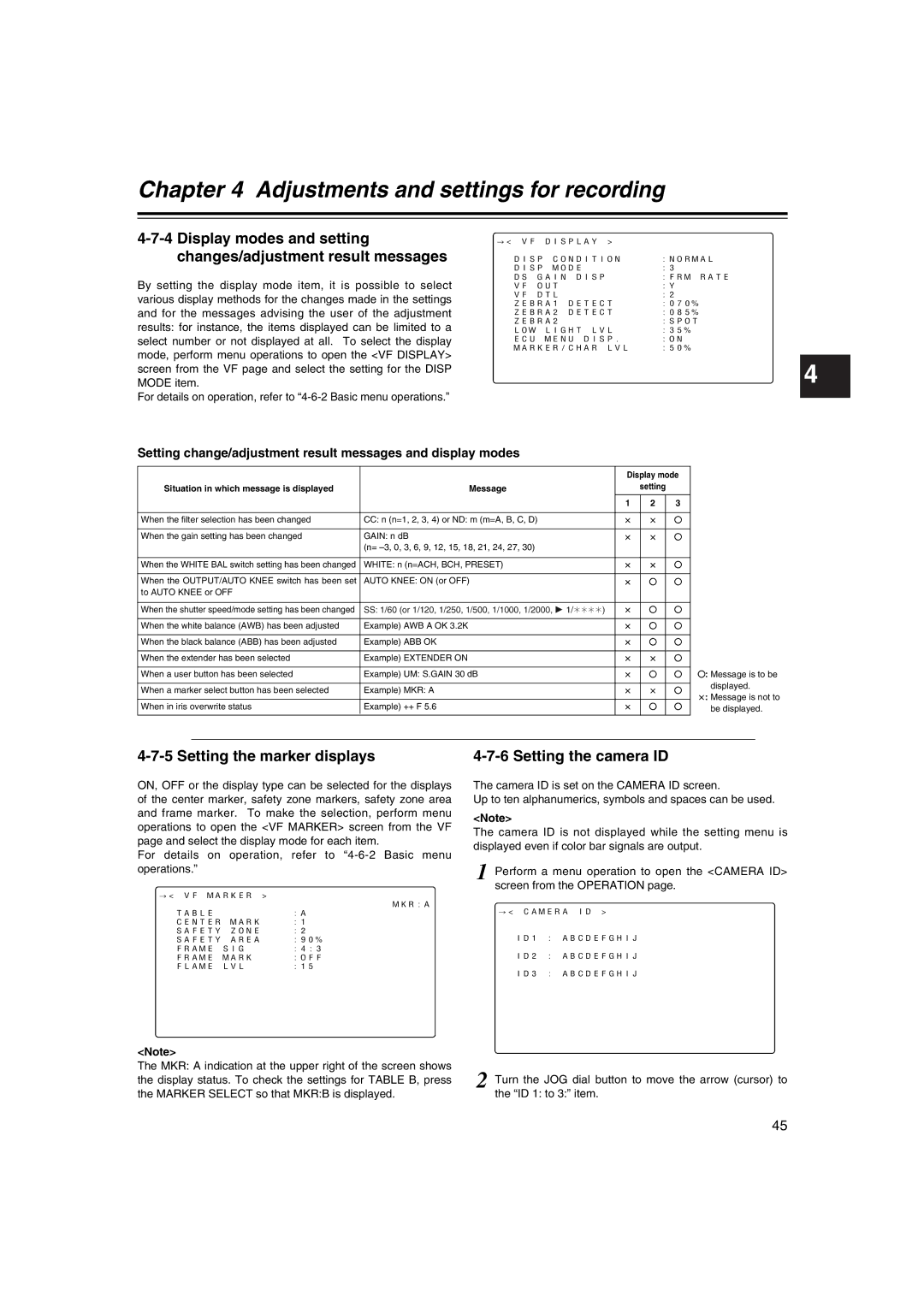
Setting change/adjustment result messages and display modes
|
| Display mode |
| |||
Situation in which message is displayed | Message |
| setting |
|
| |
|
| 1 | 2 |
| 3 |
|
|
|
|
|
|
|
|
When the filter selection has been changed | CC: n (n=1, 2, 3, 4) or ND: m (m=A, B, C, D) | a | a |
| ± |
|
|
|
|
|
|
|
|
When the gain setting has been changed | GAIN: n dB | a | a |
| ± |
|
| (n= |
|
|
|
|
|
|
|
|
|
|
|
|
When the WHITE BAL switch setting has been changed | WHITE: n (n=ACH, BCH, PRESET) | a | a |
| ± |
|
|
|
|
|
|
|
|
When the OUTPUT/AUTO KNEE switch has been set | AUTO KNEE: ON (or OFF) | a | ± |
| ± |
|
to AUTO KNEE or OFF |
|
|
|
|
|
|
|
|
|
|
|
|
|
When the shutter speed/mode setting has been changed | SS: 1/60 (or 1/120, 1/250, 1/500, 1/1000, 1/2000, 1 1/¢¢¢¢) | a | ± |
| ± |
|
|
|
|
|
|
|
|
When the white balance (AWB) has been adjusted | Example) AWB A OK 3.2K | a | ± |
| ± |
|
|
|
|
|
|
|
|
When the black balance (ABB) has been adjusted | Example) ABB OK | a | ± |
| ± |
|
|
|
|
|
|
|
|
When the extender has been selected | Example) EXTENDER ON | a | a |
| ± |
|
|
|
|
|
|
| ±: Message is to be |
When a user button has been selected | Example) UM: S.GAIN 30 dB | a | ± |
| ± | |
|
|
|
|
|
| displayed. |
When a marker select button has been selected | Example) MKR: A | a | a |
| ± | |
| a: Message is not to | |||||
|
|
|
|
|
| |
When in iris overwrite status | Example) ++ F 5.6 | a | ± |
| ± | |
| be displayed. | |||||
4-7-5 Setting the marker displays
ON, OFF or the display type can be selected for the displays of the center marker, safety zone markers, safety zone area and frame marker. To make the selection, perform menu operations to open the <VF MARKER> screen from the VF page and select the display mode for each item.
For details on operation, refer to
#< VF MARKER > | MKR:A |
| |
TABLE | :A |
CENTER MARK | :1 |
SAFETY ZONE | :2 |
SAFETY AREA | :90% |
FRAME SIG | :4:3 |
FRAME MARK | :OFF |
FLAME LVL | :15 |
4-7-6 Setting the camera ID
The camera ID is set on the CAMERA ID screen.
Up to ten alphanumerics, symbols and spaces can be used.
<Note>
The camera ID is not displayed while the setting menu is displayed even if color bar signals are output.
1 Perform a menu operation to open the <CAMERA ID> screen from the OPERATION page.
#< CAMERA ID >
ID1 : ABCDEFGHIJ
ID2 : ABCDEFGHIJ
ID3 : ABCDEFGHIJ
<Note> |
|
The MKR: A indication at the upper right of the screen shows | 2 Turn the JOG dial button to move the arrow (cursor) to |
the display status. To check the settings for TABLE B, press | |
the MARKER SELECT so that MKR:B is displayed. | the “ID 1: to 3:” item. |
45