Chapter 2 Parts and their functions
Remaining tape and remaining battery charge and
audio channel level displays | 2 |
|
1 ![]() 2
2
4
3
5
6
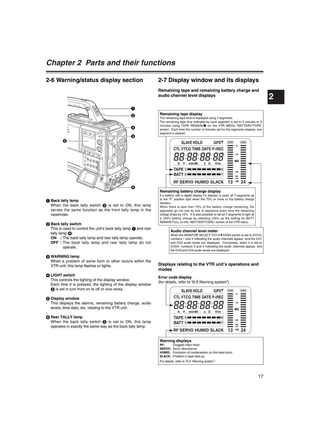
1 Back tally lamp
When the back tally switch 2 is set to ON, this lamp serves the same function as the front tally lamp in the viewfinder.
2 Back tally switch
This is used to control the unit’s back tally lamp 1 and rear tally lamp 6.
ON : The back tally lamp and rear tally lamp operate.
OFF : The back tally lamp and rear tally lamp do not operate.
3 WARNING lamp
When a problem of some form or other occurs within the VTR unit, this lamp flashes or lights.
4 LIGHT switch
This controls the lighting of the display window.
Each time it is pressed, the lighting of the display window 5 is set in turn from on to off or vice versa.
5 Display window
This displays the alarms, remaining battery charge, audio levels, time data, etc. relating to the VTR unit.
6 Rear TALLY lamp
When the back tally switch 2 is set to ON, this lamp operates in exactly the same way as the back tally lamp.
Remaining tape display
The remaining tape time is displayed using 7 segments.
The remaining tape time indicated by each segment is set to 3 minutes or 5 minutes using TAPE REMAIN/∫ on the VTR MENU “BATTERY/TAPE” screen. Each time the number of minutes set for the segments elapses, one segment is cleared.
SLAVE HOLD |
|
| GPS | OVER | OVER |
CTL VTCG TIME DATE |
| 0 | |||
|
| ||||
|
|
|
|
| 10 |
h Y minM | s | D | frm |
| 18 |
|
| ||||
TAPE E |
|
| B |
| 30 |
BATT E |
|
| F |
| |
|
|
| 40 | ||
|
|
|
|
| OO |
RF SERVO HUMID SLACK | 13 | ||||
Remaining battery charge display
If a battery with a digital display (% display) is used, all 7 segments up to the “F” position light when the 70% or more of the battery charge remains.
When there is less than 70% of the battery charge remaining, the segments go out one by one in sequence every time the remaining charge drops by 10%. It is also possible to set all 7 segments to light at a 100% battery charge by selecting 100% as the setting for BATT REMAIN FULL on the <BATTERY/TAPE> screen of the VTR menu.
Audio channel level meter
When the MONITOR SELECT CH1/2OCH3/4 switch is set to CH1/2, numbers 1 and 2 indicating the audio channels appear, and the CH1 and CH2 audio levels are displayed. Conversely, when it is set to CH3/4, numbers 3 and 4 indicating the audio channels appear, and the CH3 and CH4 audio levels are displayed.
Displays relating to the VTR unit’s operations and modes
Error code display
(for details, refer to
| SLAVE HOLD |
| GPS |
| OVER | 0 |
| OVER | |||||||||||||||||||
CTL VTCG TIME DATE |
|
|
|
| |||||||||||||||||||||||
|
| 10 |
|
| |||||||||||||||||||||||
|
|
|
| ||||||||||||||||||||||||
|
|
|
|
|
|
|
|
|
|
|
|
|
|
|
|
|
|
|
|
|
|
|
|
|
| ||
|
|
|
|
|
|
|
|
|
|
|
|
|
|
|
|
|
|
|
|
|
|
|
|
|
| ||
|
|
|
|
|
|
|
|
|
|
|
|
|
|
|
|
|
|
|
|
|
|
|
|
| |||
|
|
|
|
|
|
|
|
|
|
|
|
|
|
|
|
|
|
|
|
|
|
|
|
|
|
|
|
|
|
|
|
|
|
|
|
|
|
|
|
|
|
|
|
|
|
|
|
|
|
|
|
|
|
|
|
|
|
|
|
|
|
|
|
|
|
|
|
|
|
|
|
|
|
|
|
|
|
|
|
|
|
|
|
| h Y |
|
| minM |
|
|
| s D |
| frm |
|
| 18 |
|
| ||||||||||||
|
|
|
|
|
|
|
|
|
| ||||||||||||||||||
|
|
|
|
|
|
|
|
|
|
|
|
| |||||||||||||||
TAPE |
|
|
|
|
|
|
|
|
|
|
|
|
|
|
|
|
|
|
|
|
|
|
|
|
|
| |
E |
|
|
|
|
|
|
|
|
|
|
|
|
|
|
|
| B |
|
| 30 |
|
| |||||
BATT |
|
|
|
|
|
|
|
|
|
|
|
|
|
|
|
|
|
|
|
|
|
|
|
| |||
E |
|
|
|
|
|
|
|
|
|
|
|
|
|
|
|
| F |
|
| 40 |
|
| |||||
|
|
|
|
|
|
|
|
|
|
|
|
|
|
|
|
|
| ||||||||||
|
|
|
|
|
|
|
|
|
|
|
|
|
|
|
|
|
|
|
|
|
|
| |||||
| OO |
RF SERVO HUMID SLACK | 13 |
Warning displays
RF: Clogged video head
SERVO: Servo disturbance
HUMID: Formation of condensation on the head drum
SLACK: Problem in tape
For details, refer to
17