Chapter 7 Menu description tables
7-1 Menu configuration
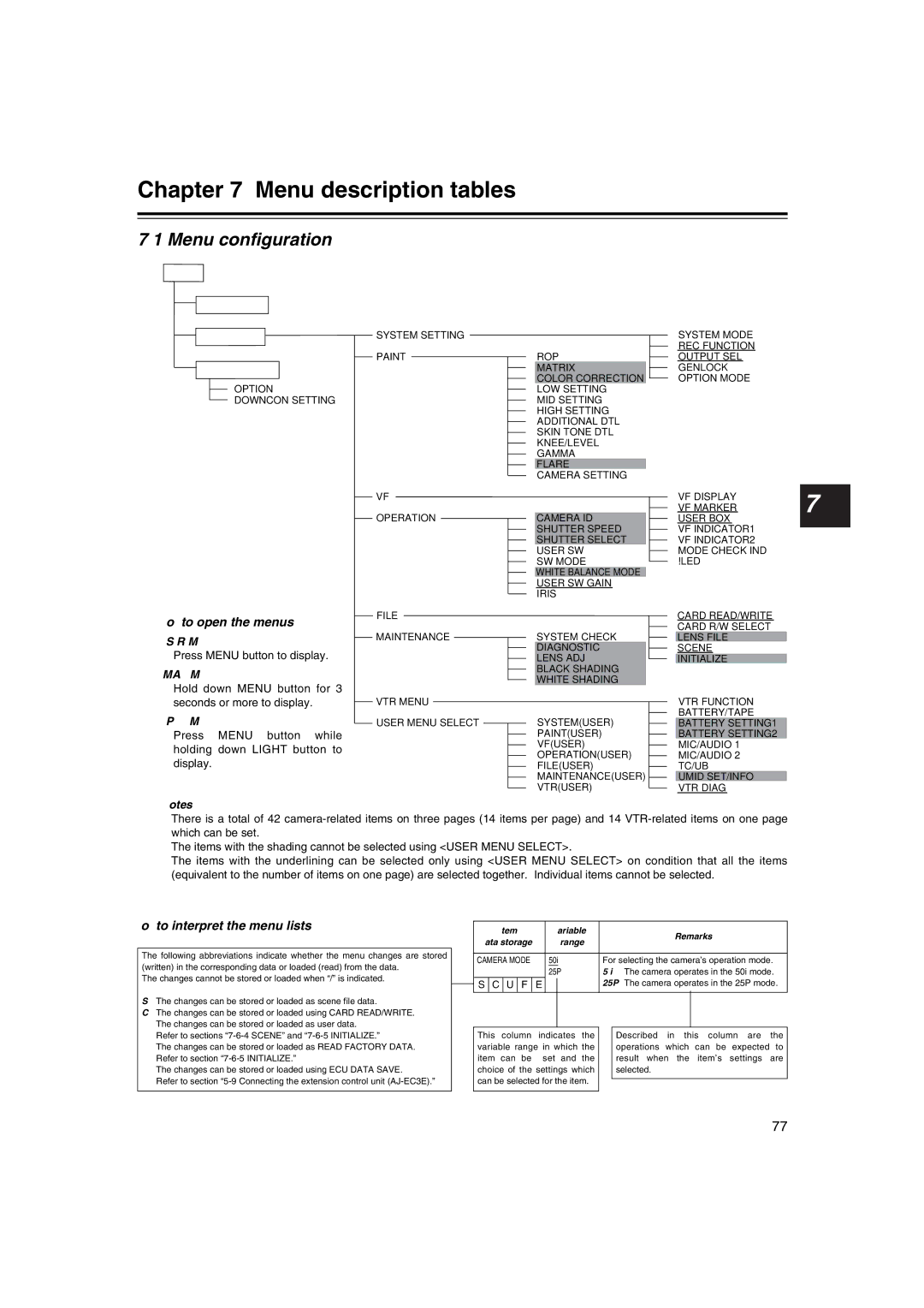
MENU
USER MENU
MAIN MENU
OPTION MENU
OPTION
DOWNCON SETTING
How to open the menus
USER MENU:
Press MENU button to display.
MAIN MENU:
Hold down MENU button for 3 seconds or more to display.
OPTION MENU:
Press MENU button while holding down LIGHT button to display.
SYSTEM SETTING
PAINTROP MATRIX
COLOR CORRECTION LOW SETTING
MID SETTING
HIGH SETTING ADDITIONAL DTL SKIN TONE DTL KNEE/LEVEL GAMMA FLARE CAMERA SETTING
VF
OPERATIONCAMERA ID SHUTTER SPEED SHUTTER SELECT USER SW
SW MODE
WHITE BALANCE MODE
USER SW GAIN
IRIS
FILE
MAINTENANCESYSTEM CHECK DIAGNOSTIC LENS ADJ BLACK SHADING WHITE SHADING
VTR MENU
USER MENU SELECTSYSTEM(USER) PAINT(USER) VF(USER)
OPERATION(USER)
FILE(USER)
MAINTENANCE(USER)
VTR(USER)
SYSTEM MODE
REC FUNCTION
OUTPUT SEL
GENLOCK
OPTION MODE
VF DISPLAY
VF MARKER7 USER BOX
VF INDICATOR1 VF INDICATOR2 MODE CHECK IND !LED
CARD READ/WRITE
CARD R/W SELECT
LENS FILE
SCENE
INITIALIZE
VTR FUNCTION
BATTERY/TAPE
BATTERY SETTING1
BATTERY SETTING2
MIC/AUDIO 1
MIC/AUDIO 2
TC/UB
UMID SET/INFO
VTR DIAG
<Notes>
≥There is a total of 42
≥The items with the shading cannot be selected using <USER MENU SELECT>.
≥The items with the underlining can be selected only using <USER MENU SELECT> on condition that all the items (equivalent to the number of items on one page) are selected together. Individual items cannot be selected.
How to interpret the menu lists
The following abbreviations indicate whether the menu changes are stored (written) in the corresponding data or loaded (read) from the data.
The changes cannot be stored or loaded when “/” is indicated.
S:The changes can be stored or loaded as scene file data.
C:The changes can be stored or loaded using CARD READ/WRITE.
U:The changes can be stored or loaded as user data. Refer to sections
F:The changes can be stored or loaded as READ FACTORY DATA. Refer to section
E:The changes can be stored or loaded using ECU DATA SAVE.
Refer to section
|
| Item/ |
| Variable |
| Remarks | |||||
| Data storage |
|
| range |
| ||||||
|
|
|
|
|
| ||||||
|
|
|
|
|
|
|
|
|
|
|
|
| CAMERA MODE |
| 50i | For selecting the camera’s operation mode. | |||||||
|
|
|
|
|
|
| 25P | 50i: The camera operates in the 50i mode. | |||
| S | C | U | F | E |
|
| 25P: The camera operates in the 25P mode. | |||
|
|
| |||||||||
|
|
|
|
|
|
|
|
|
|
| |
| This column | indicates the |
| Described in this column are the | |||||||
| variable range in which the |
| operations which can be expected to | ||||||||
| item can be | set and the |
| result when the item’s settings are | |||||||
| choice of the settings which |
| selected. | ||||||||
| can be selected for the item. |
|
|
| |||||||
|
|
|
| ||||||||
|
|
|
|
|
|
|
|
|
|
|
|
77