Chapter 4 Adjustments and settings for recording
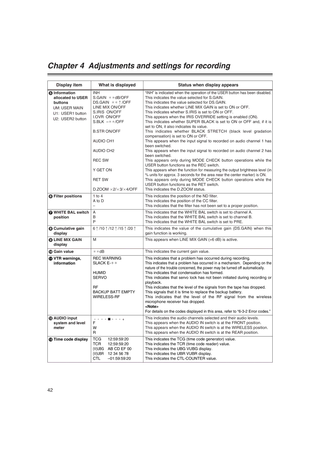
Display item | What is displayed | Status when display appears | ||
|
|
|
| |
|
|
|
| |
5 Information | INH |
| “INH” is indicated when the operation of the USER button has been disabled. | |
allocated to USER | S.GAIN | ¢¢dB/OFF | This indicates the value selected for S.GAIN. | |
buttons | DS.GAIN ¢¢:/OFF | This indicates the value selected for DS.GAIN. | ||
UM: USER MAIN | LINE MIX ON/OFF | This indicates whether LINE MIX GAIN is set to ON or OFF. | ||
U1: USER1 button | S.IRIS | ON/OFF | This indicates whether S.IRIS is set to ON or OFF. | |
I.OVR ON/OFF | This appears when the IRIS OVERRIDE setting is enabled (ON). | |||
U2: USER2 button | ||||
S.BLK | This indicates whether SUPER BLACK is set to ON or OFF and, if it is | |||
| ||||
|
|
| set to ON, it also indicates its value. | |
| B.STR ON/OFF | This indicates whether BLACK STRETCH (black level gradation | ||
|
|
| compensation) is set to ON or OFF. | |
| AUDIO CH1 | This appears when the input signal to recorded on audio channel 1 has | ||
|
|
| been switched. | |
| AUDIO CH2 | This appears when the input signal to recorded on audio channel 2 has | ||
|
|
| been switched. | |
| REC SW | This appears only during MODE CHECK button operations while the | ||
|
|
| USER button functions as the REC switch. | |
| Y GET ON | This appears when the function for measuring the output brightness level (in | ||
|
|
| % units for approx. 3 seconds for the area near the center marker) is ON. | |
| RET SW | This appears only during MODE CHECK button operations while the | ||
|
|
| USER button functions as the RET switch. | |
| D.ZOOM a2/a3/a4/OFF | This indicates the D.ZOOM status. | ||
|
|
|
| |
6 Filter positions | 1 to 4 |
| This indicates the position of the ND filter. | |
| A to D |
| This indicates the position of the CC filter. | |
| – |
| This indicates that the filter has not been set to a proper position. | |
|
|
|
| |
7 WHITE BAL switch | A |
| This indicates that the WHITE BAL switch is set to channel A. | |
position | B |
| This indicates that the WHITE BAL switch is set to channel B. | |
| P |
| This indicates that the WHITE BAL switch is set to PRE. | |
|
|
| ||
8 Cumulative gain | 6:/10:/12:/15:/20: | This indicates the value of the cumulative gain (DS.GAIN) when this | ||
display |
|
| gain function is working. | |
|
|
|
| |
9 LINE MIX GAIN | M |
| This appears when LINE MIX GAIN (+6 dB) is active. | |
display |
|
|
| |
|
|
|
| |
: Gain value | ¢¢dB |
| This indicates the current gain value. | |
|
|
| ||
; VTR warnings, | REC WARNING | This indicates that a problem has occurred during recording. | ||
information | SLACK | This indicates that a problem has occurred in a mechanism. Depending on the | ||
|
|
| nature of the trouble concerned, the power may be turned off automatically. | |
| HUMID |
| This indicates that condensation has formed. | |
| SERVO | This indicates that servo lock has not been initiated during recording or | ||
|
|
| playback. | |
| RF |
| This indicates that the level of the signals from the tape has dropped. | |
| BACKUP BATT EMPTY | This signals that it is time to replace the backup battery. | ||
|
| This indicates that the level of the RF signal from the wireless | ||
|
|
| microphone receiver has dropped. | |
|
|
| <Note> | |
|
|
| For details on the codes displayed in this area, refer to | |
|
|
| ||
< AUDIO input | This indicates the audio channels selected and their audio levels. | |||
system and level | F |
| This appears when the AUDIO IN switch is at the FRONT position. | |
meter | W |
| This appears when the AUDIO IN switch is at the WIRELESS position. | |
| R |
| This appears when the AUDIO IN switch is at the REAR position. | |
|
|
|
| |
= Time code display | TCG | 12:59:59:20 | This indicates the TCG (time code generator) value. | |
| TCR | 12:59:59:20 | This indicates the TCR (time code reader) value. | |
| (V)UBG | AB CD EF 00 | This indicates the UBG VUBG display. | |
| (V)UBR | 12 34 56 78 | This indicates the UBR VUBR display. | |
| CTL | This indicates the | ||
|
|
|
| |
42