Connections
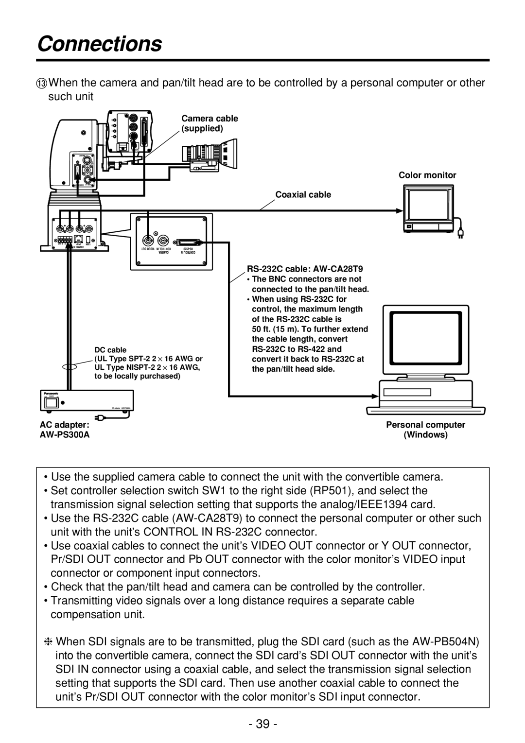
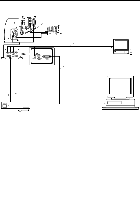
=When the camera and pan/tilt head are to be controlled by a personal computer or other such unit
Camera cable (supplied)
Color monitor
Coaxial cable
DC cable
(UL Type
•The BNC connectors are not connected to the pan/tilt head.
•When using
50 ft. (15 m). To further extend the cable length, convert
AC adapter: | Personal computer |
| (Windows) |
•Use the supplied camera cable to connect the unit with the convertible camera.
•Set controller selection switch SW1 to the right side (RP501), and select the transmission signal selection setting that supports the analog/IEEE1394 card.
•Use the
•Use coaxial cables to connect the unit’s VIDEO OUT connector or Y OUT connector, Pr/SDI OUT connector and Pb OUT connector with the color monitor’s VIDEO input connector or component input connectors.
•Check that the pan/tilt head and camera can be controlled by the controller.
•Transmitting video signals over a long distance requires a separate cable compensation unit.
❈When SDI signals are to be transmitted, plug the SDI card (such as the
- 39 -