Connections
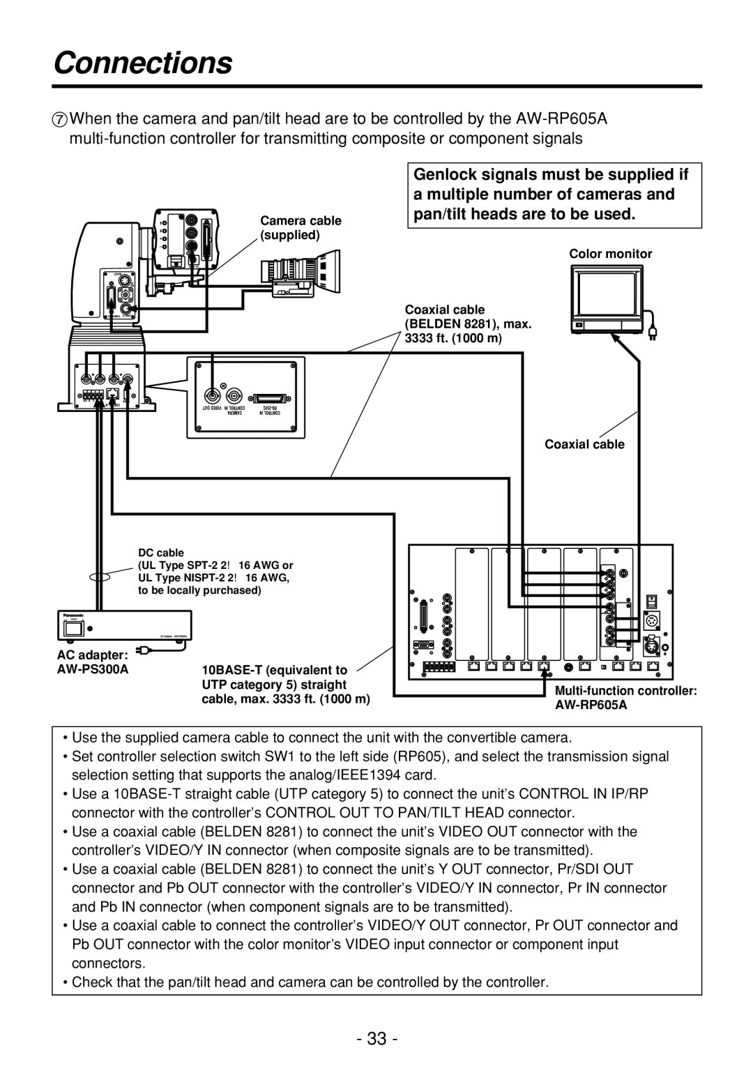
7When the camera and pan/tilt head are to be controlled by the
Camera cable (supplied)
Genlock signals must be supplied if a multiple number of cameras and pan/tilt heads are to be used.
Color monitor
Coaxial cable (BELDEN 8281), max. 3333 ft. (1000 m)
Coaxial cable
DC cable
(UL Type
AC adapter: |
|
|
|
| |
| UTP category 5) straight | |
| cable, max. 3333 ft. (1000 m) | |
|
| |
|
|
•Use the supplied camera cable to connect the unit with the convertible camera.
•Set controller selection switch SW1 to the left side (RP605), and select the transmission signal selection setting that supports the analog/IEEE1394 card.
•Use a
•Use a coaxial cable (BELDEN 8281) to connect the unit’s VIDEO OUT connector with the controller’s VIDEO/Y IN connector (when composite signals are to be transmitted).
•Use a coaxial cable (BELDEN 8281) to connect the unit’s Y OUT connector, Pr/SDI OUT connector and Pb OUT connector with the controller’s VIDEO/Y IN connector, Pr IN connector and Pb IN connector (when component signals are to be transmitted).
•Use a coaxial cable to connect the controller’s VIDEO/Y OUT connector, Pr OUT connector and Pb OUT connector with the color monitor’s VIDEO input connector or component input connectors.
•Check that the pan/tilt head and camera can be controlled by the controller.
- 33 -