Connections
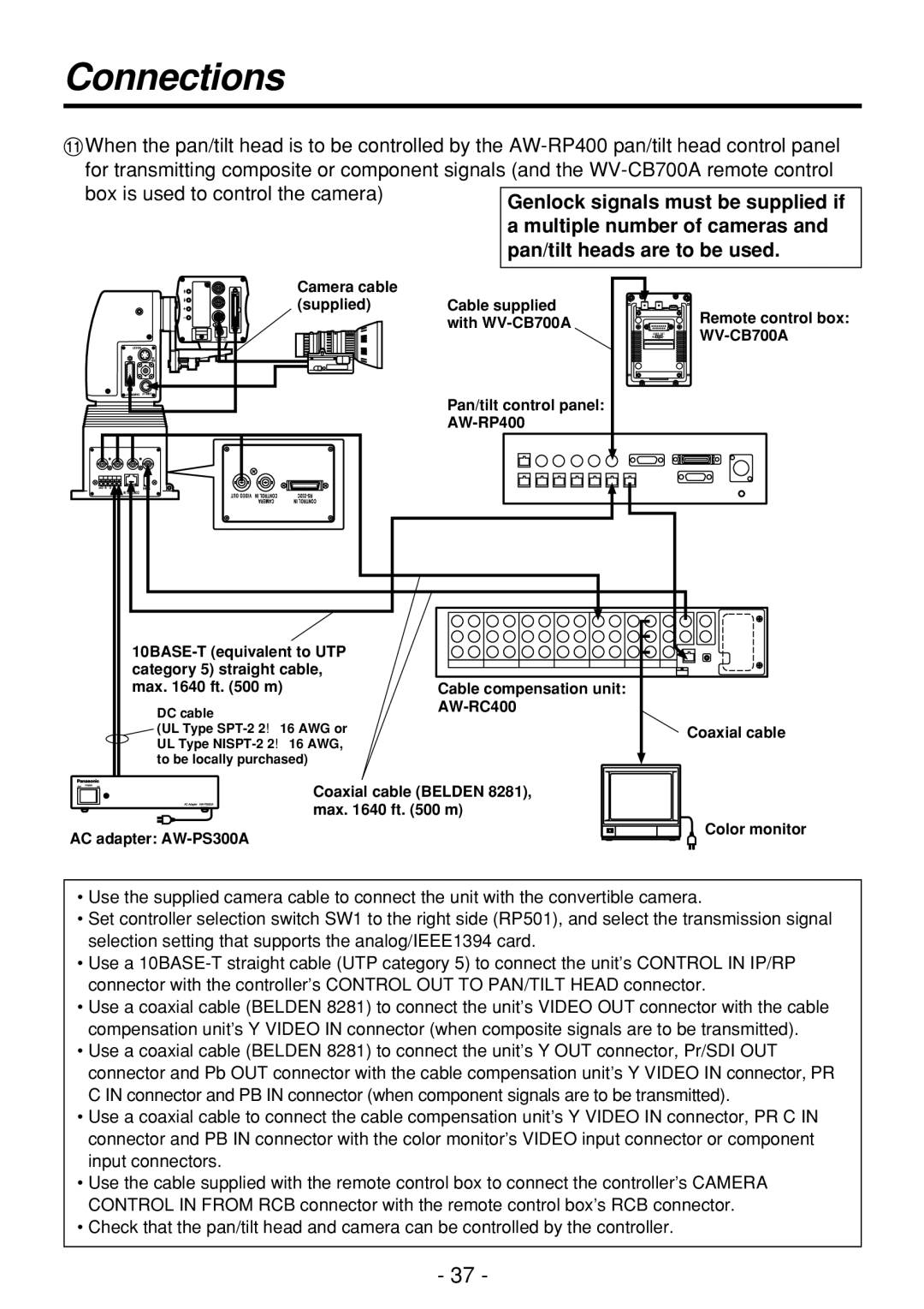
;When the pan/tilt head is to be controlled by the
Camera cable
(supplied) Cable supplied with
Pan/tilt control panel:
Remote control box:
|
|
|
|
|
|
|
|
|
|
|
|
|
|
|
| |
category 5) straight cable, |
|
|
|
|
|
|
|
|
|
|
|
|
|
|
|
|
max. 1640 ft. (500 m) | Cable compensation unit: | |||||||||||||||
DC cable |
| |||||||||||||||
|
|
|
|
|
|
|
|
|
|
|
|
|
|
|
| |
(UL Type |
|
|
|
|
|
|
|
|
|
|
|
|
|
|
|
|
UL Type |
|
|
|
|
|
|
|
|
|
|
|
|
|
|
|
|
to be locally purchased) |
|
|
|
|
|
|
|
|
|
|
|
|
|
|
|
|
Coaxial cable (BELDEN 8281), max. 1640 ft. (500 m)
AC adapter: AW-PS300A
Coaxial cable
Color monitor
•Use the supplied camera cable to connect the unit with the convertible camera.
•Set controller selection switch SW1 to the right side (RP501), and select the transmission signal selection setting that supports the analog/IEEE1394 card.
•Use a
•Use a coaxial cable (BELDEN 8281) to connect the unit’s VIDEO OUT connector with the cable compensation unit’s Y VIDEO IN connector (when composite signals are to be transmitted).
•Use a coaxial cable (BELDEN 8281) to connect the unit’s Y OUT connector, Pr/SDI OUT connector and Pb OUT connector with the cable compensation unit’s Y VIDEO IN connector, PR C IN connector and PB IN connector (when component signals are to be transmitted).
•Use a coaxial cable to connect the cable compensation unit’s Y VIDEO IN connector, PR C IN connector and PB IN connector with the color monitor’s VIDEO input connector or component input connectors.
•Use the cable supplied with the remote control box to connect the controller’s CAMERA CONTROL IN FROM RCB connector with the remote control box’s RCB connector.
•Check that the pan/tilt head and camera can be controlled by the controller.
- 37 -