Connections
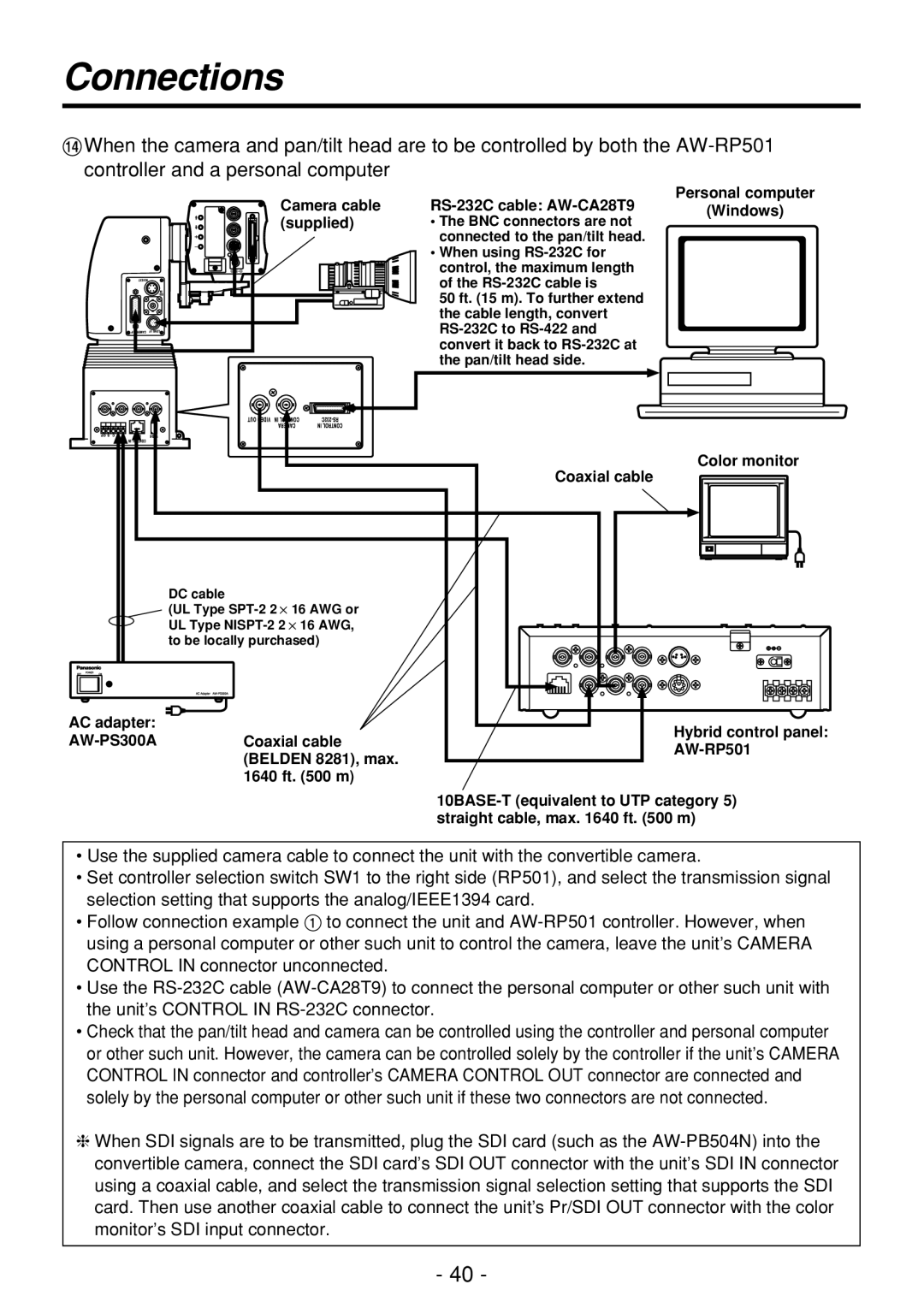
>When the camera and pan/tilt head are to be controlled by both the
Camera cable (supplied)
RS-232C cable: AW-CA28T9
•The BNC connectors are not connected to the pan/tilt head.
•When using
50 ft. (15 m). To further extend the cable length, convert
Personal computer
(Windows)
AC adapter: AW-PS300A
| Color monitor | |
| Coaxial cable | |
DC cable |
| |
(UL Type |
| |
UL Type |
| |
to be locally purchased) |
| |
Coaxial cable | Hybrid control panel: | |
(BELDEN 8281), max. | ||
| ||
1640 ft. (500 m) |
|
•Use the supplied camera cable to connect the unit with the convertible camera.
•Set controller selection switch SW1 to the right side (RP501), and select the transmission signal selection setting that supports the analog/IEEE1394 card.
•Follow connection example 1 to connect the unit and
•Use the
•Check that the pan/tilt head and camera can be controlled using the controller and personal computer or other such unit. However, the camera can be controlled solely by the controller if the unit’s CAMERA CONTROL IN connector and controller’s CAMERA CONTROL OUT connector are connected and solely by the personal computer or other such unit if these two connectors are not connected.
❈When SDI signals are to be transmitted, plug the SDI card (such as the
- 40 -