Manuals
/
Panasonic
/
Computer Equipment
/
Network Card
Panasonic
AW-PH360N
manual
Parts and their functions
Models:
AW-PH360N
1
7
52
52
Download
52 pages
54.4 Kb
4
5
6
7
8
9
10
11
<
>
Specs
Install
$ Head connector panel
$ Replacing the battery
OAdjusting slack in the chain
Osdi settings
Precautions for use
Safety
Page 7
Image 7
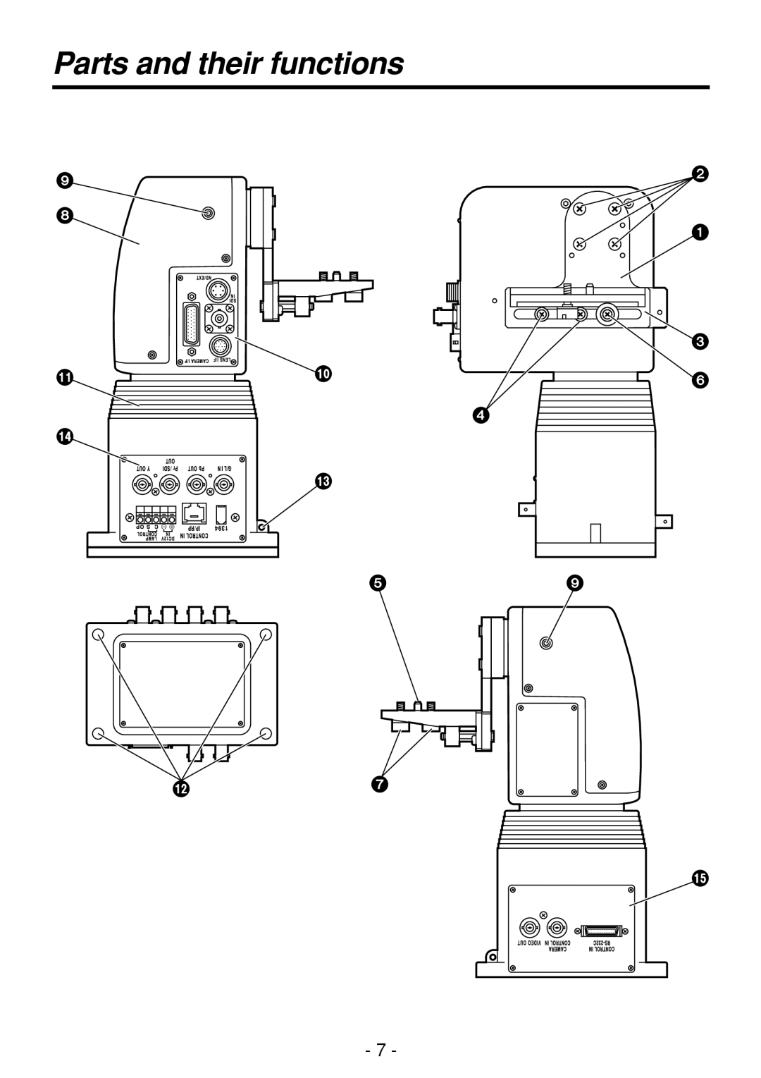
Parts and their functions
- 7 -
Page 6
Page 8
Page 7
Image 7
Page 6
Page 8
Contents
AW-PH360N
Indicates safety information
FCC Note
Accessories
Contents
Introduction
Installation precautions
Precautions for use
Parts and their functions
Tilting arm
$ Assembling the pan/tilt head
Suspended installation Stand-alone installation
OAttaching the tilting arm
For a precise landing
For suspended installation
For stand-alone installation
For a soft landing
Connector printed circuit board
$ Transmission signal selection setting
OAnalog/IEEE1394 card settings Oweb card settings
Osdi settings
When using the AW-RP605A controller
$ Setting the cable compensation circuit of video signals
When using the AW-RP400 controller
$ Installing the pan/tilt head
$ Mounting the camera
Suspended installation
Mounting example when the lens side is heavy
Mounting example when the camera side is heavy
With the AW-E350/AW-E650
OAttaching the chain
With the AW-E655/AW-E750/AW-E860
OMounting a camera
OAdjusting slack in the chain
With the AW-E350/AW-E650 With the AW-E655/AW-E750/AW-E860
Connections
Monitor
Connections
Compensation unit
Zoom lens RS-232C cable AW-CA28T9
$ Connecting the connector panel RS-232C control
As viewed from cable end
$ Head connector panel
Connector
Pb OUT connector
DC 12V in terminal board
$ Connecting the AC adapter for use with the pan/tilt head
10BASE-T
$ Connection examples
AW-PS300A
AC adapter AW-PS300A
Equivalent to UTP Category 5 straight Cable, max ft 10 m
Equivalent to
Belden
AW-RP605A
Coaxial cable Camera cable supplied
Panel is used to control the camera
Coaxial cable Belden 8281, max ft m Color monitor
AW-RC400
Connections
Personal computer
Belden 8281, max
AW-CA50F29
AW-CA50E29
Limiters
OFor the controller AW-RP301/AW-RP305/AW-RP501/AW-RP505
$ Setting/releasing the limiters
OFor the controller AW-RP605A
OFor the controller AW-RP400
$ Replacing the gear
Replacement of consumable parts
$ Replacing the battery
$ Replacing the motor
Specifications
$ Functions/performance
Page
Page
Panasonic Broadcast & Television Systems Company
Top
Page
Image
Contents