PT-DW7000U
Commercial Use
Dear Panasonic Customer
Model number PT-D7700U / PT-DW7000U
Page
Contents
Precautions with regard to safety
Do not place liquid containers on top of the projector
Insulate the battery using tape or similar before disposal
Use only the Specified battery
Do not insert any foreign objects into the projector
Do not use the old lamp unit
Accessories
Do not look into the lens while the projector is being used
Precautions on handling
Examples of system expansion
Name and function of parts
Remote control
When the operation mode selector is set to Projector
When the operation mode selector is set to Computer
Front and side of the projector
Rear view of the main unit Controls on rear panel
Video OUT terminal
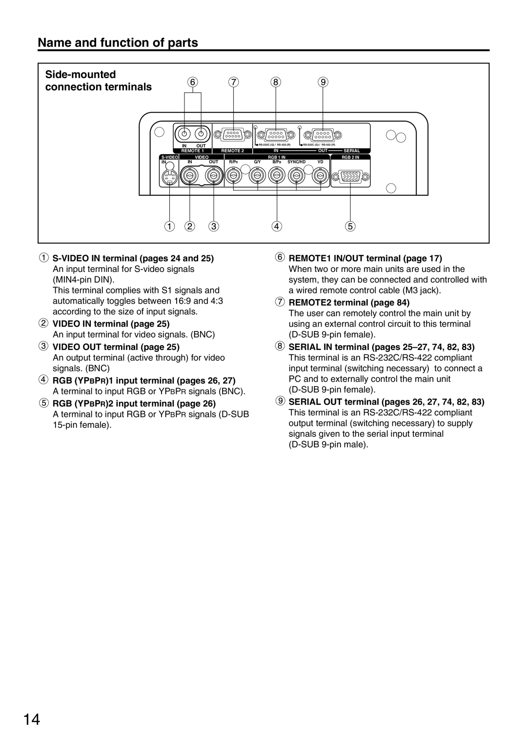
Side-mounted connection terminals
Video in terminal
RGB YPBPR1 input terminal pages 26
Loading dry cells
Using the remote control unit
Effective range of remote control operation
Setting projector ID number to remote control
Operation mode selector switch
Using the remote control as a PC mouse
Using a wired remote control
Installation geometry
Installation
Adjusting the leveling feet
Projection scheme
Projection distance SH Effective screen height
Installation
11810
ET-D75LE3
Aspect ratio Projection distance L formula Units m
· SYNC/Y SDA HD/SYNC SCL
Connection
Before starting connection
Video deck TBC built-in High-vision video deck
Example of connecting with Video devices
Video deck TBC built-in Color monitor Control PC
Example of connecting with personal computers
Example of connecting with the signal selector
Signal selector
Types of the input modules optional
Installation of input module optional
Installing the input module
Procedure of installation
Connecting signals to the input module
ET-MD95RGB
RGB signal input module optional
Connecting the signal to the analog RGB signal input module
Connecting the component signals
SUB BNC
Video signal input module optional
Connecting the signal to the video signal input module
Connecting the video signals
Connecting the component signals
Serial digital input module optional
ET-MD95SD2 for 480p/480i/576i
Auto
DVI-D input module optional
Connecting signals to the DVI signal input module
Pin No Signal
How to install the projection lens
How to remove the projection lens
Press the l button. on the main unit or the remote control
Powering up the projector
Making adjustment and selection
Roughly adjust the focus of the lens. Refer to
Powering off the projector
Projection
Choose an item and adjust it using Buttons
How to adjust the lens
Adjustment range after lens position optical shift
How to adjust the lens for addressing unevenness of focusing
Automatic adjustment Auto Setup
Registration of new data
Registration of input signal data
Renaming the registered signals
Press the Menu button
Clearing the data of registered signals
Sub memory
How to register into sub memory
How to erase sub memory
Restrictions
On-screen indications
Memory no A1
Using the digital zoom D.ZOOM + function
Using the Freeze function
Using the Shutter function
On-screen menus
Structure of menu screens
Basic operations on menu screen
Menu items setting
Resetting to the factory default
Returning to the previous screen
Select Picture with the buttons Press the Enter button
Adjusting the picture
Switching the picture mode
Adjusting Contrast / Bright / Color / Tint
Select OK with Buttons Press the Enter button
Registering the picture mode settings as presettings
Select Picture with
Dynamic Iris setting
Select the Dynamic Iris setting with Buttons
Adjusting the color temperature
Operation Adjustment Remarks
Sharpness / Gamma / Noise reduction
Procedure of adjustment
Adjustment items Operation
To display pictures complying with the sRGB standard
Adjusting the position
Shift adjustment
Size adjustment
Adjust the clock phase with
Clock phase adjustment
Select Clock Phase with
Size modes
Keystone distortion correction
Adjust the Keystone horizontally With the buttons
Adjust the vertical Linearity with Buttons
Select Keystone with the buttons Press the Enter button
Format To input Betacam with YCbCr
How to use Advanced Menu
Signal level
Select Advanced Menu with the buttons Press Enter button
Blanking adjustment
Select Blanking with the buttons Press the Enter button
Adjusting the input resolution
Total DOTS, Display DOTS, Total Lines and Display Lines
Adjusting the clamp position
Select Advanced Menu with the buttons Press the Enter button
Adjustment marker
Edge blending adjustment
Specify the area to be adjusted with the buttons
Edge blending adjustment continuing
Select Advanced Menu with the buttons
Raster position
Changing the display language
When 54 pictures are displayed when Sxga signals are input
When 43 pictures are displayed
Raster position continuing
How to change the system format
How to use RGB Reality mode
Procedure of setting
Option settings
ID number setting
ID number need not be set when only one projector is used
Installation Setting
FRONT-F FRONT-C REAR-C REAR-F
Lamp power
Lamp select
System information
Press and buttons to select RS232C Setting
Position of on-screen indications
Press and buttons to select Option
Select Option with the buttons Press Enter button
Adjusting color matching
These values can be adjusted from 0 to 2 Adjustment
Select Measured Data with Buttons Press the Enter button
Adjusting the color matching using a colorimeter
Select Target Data with the buttons Press the Enter button
Using the buttons, select Auto Setup Press the Enter button
Video setting
Automatic adjustment
Using the buttons, switch to the desired mode
Fan control
Output resolution D7700U only
Auto signal
Use the buttons to select OFF, User 1, User 2, or User
List of P in P
Setting FUNC1
Password
How to change the signal for the ET-MD95VM2 optional
Communication conditions Factory setting
Using the serial terminals
Pin assignments and signal names
Examples of connection
Command
Control commands
Cable specifications
Connecting to a PC Computer Projector DTE specifications
Sub 9-pin female
Using the Remote 2 terminal
Pin assignments and control
External appearance
Cycle of displayed internal test patterns
Displaying the internal test pattern
RS-422 control functions
Select Security with the buttons Press the Enter button
Setting the security
Setting the password
Set the password with the , , and buttons
Changing the password
Setting the text
Changing the text
Hold down the Menu button for 3 or so seconds
How to use CP Option
Setting the on-screen indication function
Select CP Option with the buttons
Setting the system format
Name and function of network module parts
How to use network module optional
Example of connection
Initial setting of network module
Items Function Description
Initial setting of network module continuing
Accessing from the Web browser
Port No
Network setting
Top
Network setting Advanced control
Smtp
Mail setting
Monitor information
Mail setting page continuing
Image file control
Indication
Indication of monitor lamp
Lamp Information Checkpoint Remedial measure
Monitor
Clean the air filter
Cleaning and replacement of air filter
Procedure of cleaning
Dismantle the air filter
Replacement of lamp unit
Timing of lamp unit replacement
Procedure of lamp unit replacement
101
Option screen, and select
On the projector or the remote control
Press the Enter button to display
System Information with
Remote control does
Symptoms Checkpoint
Power does not turn on
No image appears on
Specifications
Remote control Power source
Length of power supply cord Cabinet
Outside dimensions
Video signal input module
Compatible RGB/YPBPR Signals
Appendix
Outside dimensions
Trademark Acknowledgement
Concernant LA Sécurité
Ne pas surcharger la prise de courant
Précautions concernant la sécurité
Ne pas couvrir le filtre et la sortie d’air
Ne pas retirer le couvercle ou le modifier
Ne démontez pas le bloc lampe
Ne pas placer le projecteur sur des surfaces instables
Ne pas placer des récipients de liquide sur le projecteur
Ne pas mettre d’objets étrangers dans le projecteur
Nutilisez pas un bloc lampe usagé
Ne pas placer d’objets lourds sur le projecteur
’utiliser que la pile indiquée
Mise au rebut
Nettoyage et maintenance
Précautions pour la manipulation
Remplacement de la lampe
Période de remplacement de la lampe
Procédure de remplacement de la lampe
La lampe est chaude si elle vient d’être utilisée
115
Technical Support
Panasonic Canada Inc

 VIDEO IN terminal (page 25)
 VIDEO OUT terminal (page 25)
 RGB (YPBPR)1 input terminal (pages 26, 27)
 RGB (YPBPR)2 input terminal (page 26)