4. Setting the Switches
The
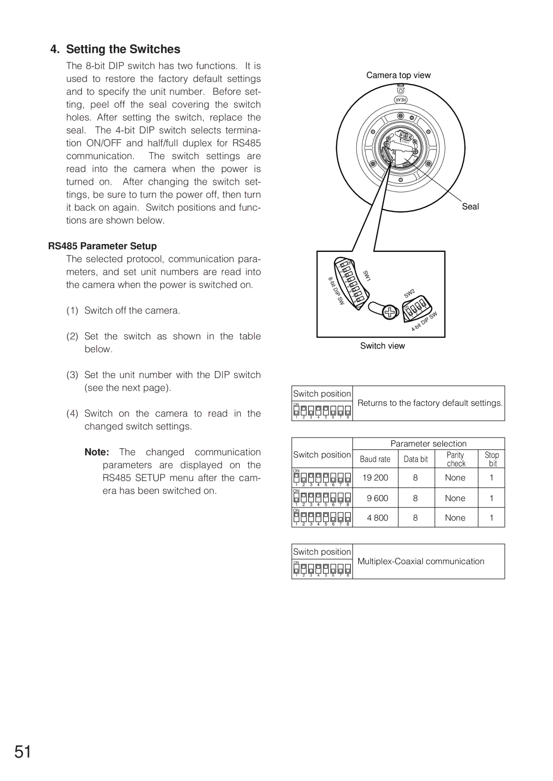
RS485 Parameter Setup
The selected protocol, communication para- meters, and set unit numbers are read into the camera when the power is switched on.
(1)Switch off the camera.
(2)Set the switch as shown in the table below.
(3)Set the unit number with the DIP switch (see the next page).
(4)Switch on the camera to read in the changed switch settings.
Note: The changed communication parameters are displayed on the RS485 SETUP menu after the cam- era has been switched on.
Camera top view
REAR
![]() S TA RT
S TA RT
AC24VONLY SWRS485Setting 1
SW2
Seal
|
|
|
|
|
|
| O |
|
|
|
|
|
|
|
|
|
|
|
|
| N |
|
|
|
|
|
|
|
|
|
|
|
| 1 |
|
|
|
|
|
|
|
|
|
|
|
|
| 2 |
|
|
|
|
|
|
|
|
|
|
|
| 8 | 3 |
| SW1 |
|
|
|
|
|
|
|
|
|
| - | 4 |
|
|
|
|
|
| |
|
|
|
|
| bit | 5 |
|
|
|
|
|
| |
|
|
|
|
| DIP | 6 |
| SW2 |
|
|
|
| |
|
|
|
|
|
|
| 7 |
|
|
|
|
|
|
|
|
|
|
|
| SW | 8 |
|
|
|
|
|
|
|
|
|
|
|
|
|
|
| N |
| 4 |
|
|
|
|
|
|
|
|
|
|
| O | 3 |
|
| |
|
|
|
|
|
|
|
|
| 2 |
|
| SW |
|
|
|
|
|
|
|
|
|
| 1 |
|
|
| |
|
|
|
|
|
|
|
|
| DIP |
|
| ||
|
|
|
|
|
|
|
|
|
|
|
| ||
|
|
|
|
|
|
|
|
| 4 |
|
|
|
|
|
|
|
|
|
|
|
| Switch view |
|
|
|
| |
Switch position | Returns to the factory default settings. | ||||||||||||
ON |
|
|
|
|
|
|
| ||||||
1 | 2 | 3 | 4 | 5 | 6 | 7 | 8 |
|
|
|
|
|
|
|
|
|
|
|
|
|
|
| Parameter selection |
| |||
Switch position | Baud rate | Data bit | Parity | Stop | |||||||||
|
|
|
|
|
|
|
| check | bit | ||||
|
|
|
|
|
|
|
|
|
|
|
| ||
ON |
|
|
|
|
|
|
| 19 200 | 8 |
|
| None | 1 |
1 | 2 | 3 | 4 | 5 | 6 | 7 | 8 |
|
| ||||
|
|
|
|
|
| ||||||||
ON |
|
|
|
|
|
|
| 9 600 | 8 |
|
| None | 1 |
1 | 2 | 3 | 4 | 5 | 6 | 7 | 8 |
|
| ||||
|
|
|
|
|
| ||||||||
ON |
|
|
|
|
|
|
| 4 800 | 8 |
|
| None | 1 |
1 | 2 | 3 | 4 | 5 | 6 | 7 | 8 |
|
| ||||
|
|
|
|
|
| ||||||||
Switch position |
| ||||||||||||
ON |
|
|
|
|
|
|
|
| |||||
1 | 2 | 3 | 4 | 5 | 6 | 7 | 8 |
|
|
|
|
|
|
51