RS485 Setting |
|
|
|
|
|
| SW2 |
|
|
| ||||
The |
|
|
|
|
|
|
|
|
|
| ||||
ON |
|
|
|
|
|
|
|
| ||||||
RS485 termination. |
|
|
|
|
|
|
|
|
|
|
|
| ||
|
|
|
|
|
|
|
|
|
|
|
|
|
|
|
|
|
|
|
|
| 1 |
| 2 |
| 3 |
| 4 |
|
|
|
|
|
|
|
|
| ||||||||
|
|
|
|
|
|
|
|
|
|
|
|
|
|
|
|
| BP 1 |
|
| Function |
|
|
| ||||||
|
|
|
|
|
|
|
|
|
|
|
|
|
|
|
Switch |
| ON |
| Termination ON |
|
|
| |||||||
position |
| OFF |
| Termination OFF * |
| |||||||||
|
|
|
|
|
|
|
|
|
|
|
|
|
|
|
|
|
|
|
|
|
|
|
| ||||||
| BP 2 | BP 3 | BP 4 |
| Function |
|
|
| ||||||
|
|
|
|
|
|
|
|
|
|
|
|
|
|
|
Switch | ON | ON | ON | Half duplex (2 line) |
| |||||||||
position | OFF | OFF | OFF | Full duplex (4 line) * |
| |||||||||
|
|
|
|
|
|
|
|
|
|
|
|
|
|
|
Notes:
•Defaults are marked with *.
•BP stands for Bit Position.
•Full duplex is not available in a daisy chain connection. (Panasonic system controllers only)
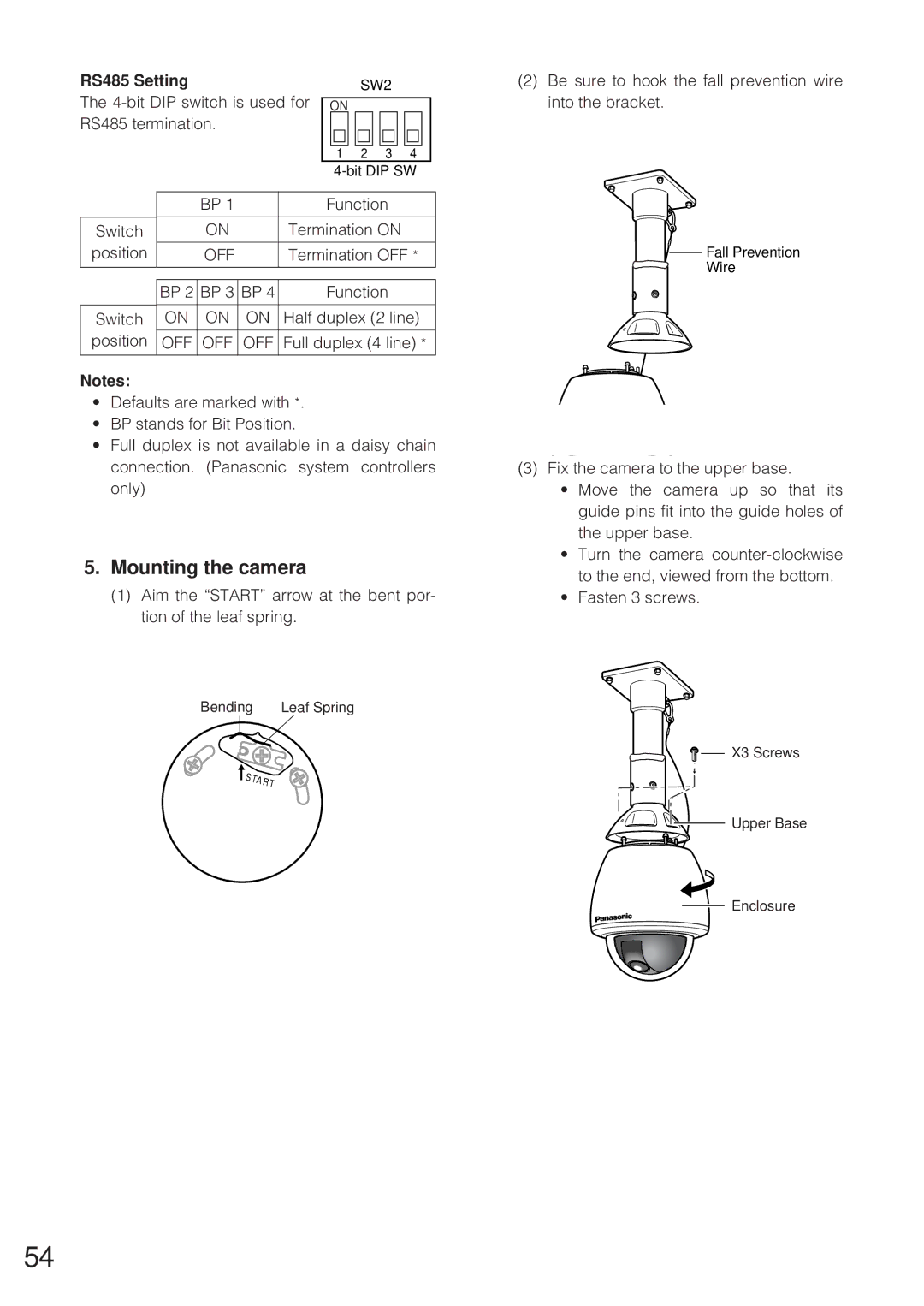
5.Mounting the camera
(1)Aim the “START” arrow at the bent por- tion of the leaf spring.
Bending | Leaf Spring |
(2)Be sure to hook the fall prevention wire into the bracket.
Fall Prevention
Wire
(3)Fix the camera to the upper base.
•Move the camera up so that its guide pins fit into the guide holes of the upper base.
•Turn the camera
•Fasten 3 screws.
![]()
![]() X3 Screws
X3 Screws
![]()
![]() Upper Base
Upper Base
Enclosure
54