CONNECTIONS
Precautions
•The following connections should be made by qualified service personnel or system installers in accordance with all local codes.
•Switch the 24 V AC power source off before installation and connection.
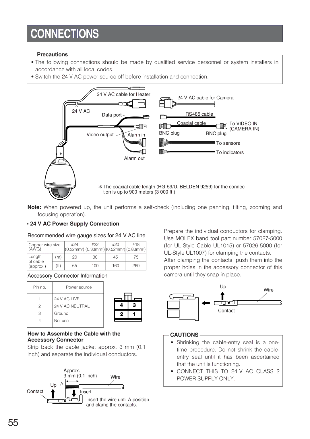
24 V AC cable for Heater
24 V AC
Data port ![]()
24 V AC cable for Camera
RS485 cable
Coaxial cable |
Video output | Alarm in | BNC plug | BNC plug |
|
|
To VIDEO IN
(CAMERA IN)
To sensors
To indicators
Alarm out
✻ The coaxial cable length
Note: When powered up, the unit performs a
• 24 V AC Power Supply Connection
Recommended wire gauge sizes for 24 V AC line
Copper wire size | #24 |
| #22 |
|
| #20 |
|
| #18 |
| |||||
(AWG) |
| (0.22mm2) | (0.33mm2) | (0.52mm2) | (0.83mm2) | ||||||||||
|
|
|
|
|
|
|
|
|
|
|
|
|
|
|
|
Length | (m) | 20 |
| 30 |
|
| 45 |
|
| 75 |
| ||||
of cable |
|
|
|
|
|
|
|
|
|
|
|
|
|
|
|
(ft) | 65 |
| 100 |
|
| 160 |
|
| 260 |
| |||||
(approx.) |
|
|
|
|
|
| |||||||||
|
|
|
|
|
|
|
|
|
|
|
|
|
|
| |
Accessory Connector Information |
|
|
|
|
|
|
|
|
| ||||||
|
|
|
|
|
|
|
|
|
|
|
|
| |||
Pin no. |
| Power source |
|
|
|
|
|
|
|
|
|
| |||
|
|
|
|
|
|
|
|
|
|
|
|
|
| ||
1 | 24 V AC LIVE |
|
|
|
|
|
|
|
|
|
|
|
| ||
|
|
|
|
|
|
|
|
|
|
|
| ||||
2 | 24 V AC NEUTRAL |
|
|
|
| 4 |
| 3 |
| ||||||
3 | Ground |
|
|
|
|
|
|
|
|
|
|
|
| ||
|
|
| 2 | 1 |
| ||||||||||
4 | Not use |
|
|
|
|
|
|
|
|
|
|
|
| ||
|
|
|
|
|
|
|
|
|
|
|
| ||||
|
|
|
|
|
|
|
|
|
|
|
| ||||
|
|
|
|
|
|
|
|
|
|
|
|
|
|
|
|
Prepare the individual conductors for clamping. Use MOLEX band tool part number
After clamping the contacts, push them into the proper holes in the accessory connector of this camera until they snap in place.
Up
Wire
Contact
How to Assemble the Cable with the Accessory Connector
Strip back the cable jacket approx. 3 mm (0.1 inch) and separate the individual conductors.
Approx.
Approx.
3 | (0.1 inch) |
| |
Wire | |||
3 mm (0.1 inch) | |||
Up A
Contact | Insert |
InsertIns the wireire untiluntilAApositpositionon
anda clampl the contactst cts..
CAUTIONS
•Shrinking the
•CONNECT THIS TO 24 V AC CLASS 2 POWER SUPPLY ONLY.
55