6.0 OPERATION
Once the Model 3088 is properly configured and installed, it should oper- ate transparently. This sections describes
6.1 POWER-UP
To apply power to the Model 3088, first be sure that you have read sec- tion 5.4, “Connecting Power” on page 32, and that the unit is connected to the appropriate power source. Power up the unit.
6.2 LED STATUS MONITORS
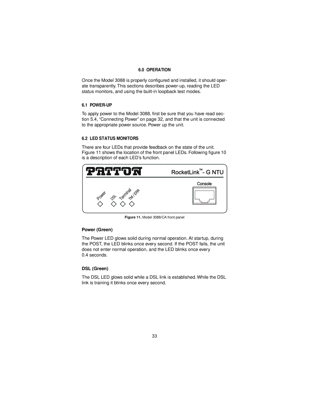
There are four LEDs that provide feedback on the state of the unit. Figure 11 shows the location of the front panel LEDs. Following figure 10 is a description of each LED’s function.
Figure 11. Model 3088/CA front panel
Power (Green)
The Power LED glows solid during normal operation. At startup, during the POST, the LED blinks once every second. If the POST fails, the unit does not enter normal operation, and the LED blinks once every
0.4 seconds.
DSL (Green)
The DSL LED glows solid while a DSL link is established. While the DSL link is training it blinks once every second.
33