05/08 Rev. AB | OPERATOR’S HANDBOOK | Setup | |
|
|
|
9844/9854
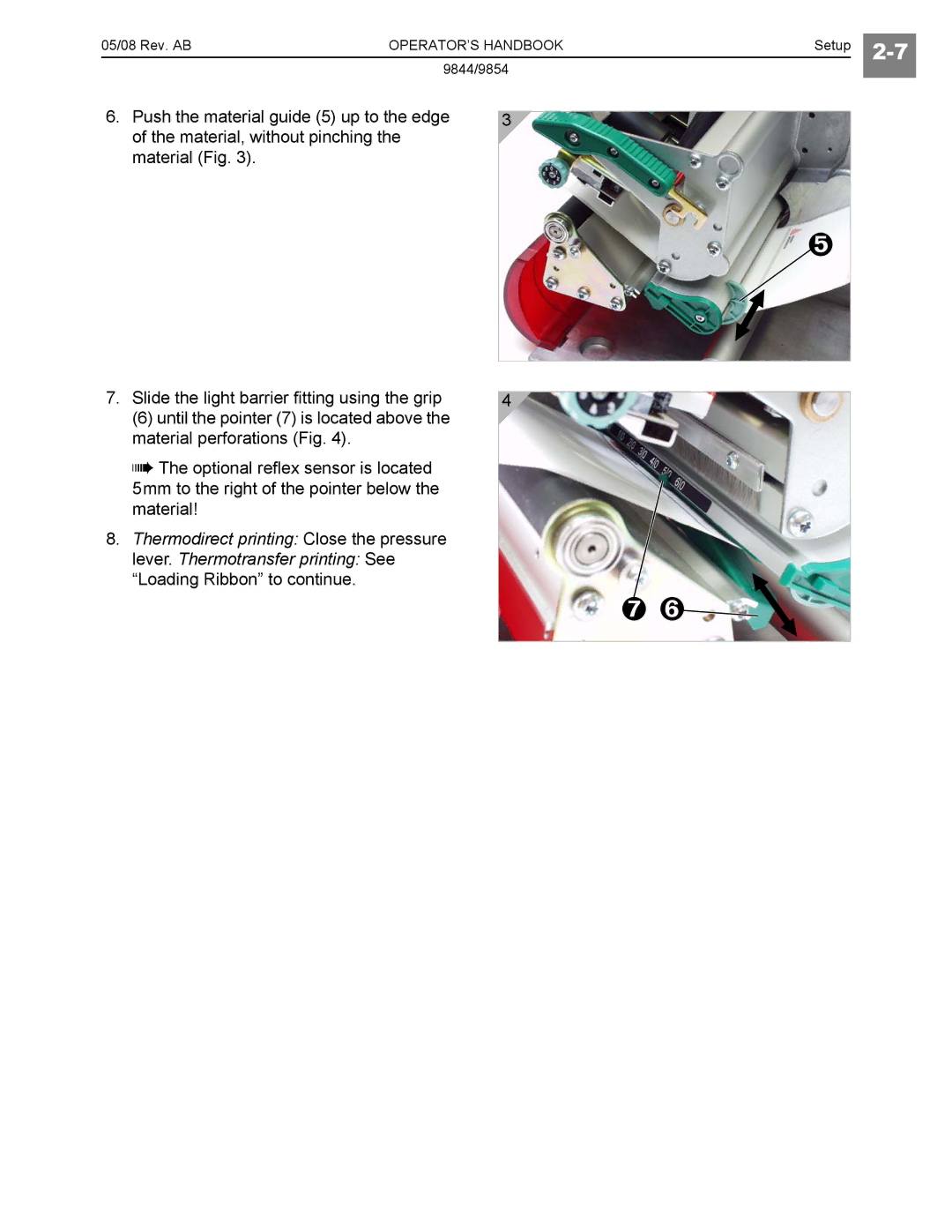
6.Push the material guide (5) up to the edge of the material, without pinching the material (Fig. 3).
7.Slide the light barrier fitting using the grip
(6) until the pointer (7) is located above the material perforations (Fig. 4).
The optional reflex sensor is located 5mm to the right of the pointer below the material!
8.Thermodirect printing: Close the pressure
lever. Thermotransfer printing: See “Loading Ribbon” to continue.
3
4
