WIRING ALARMS AND RELAYS
The DX9100 provides 16 alarm inputs and two relay outputs. Each alarm input and relay output can be matched to a video input. For example, alarm input 5 can match video input 3 and relay 1.
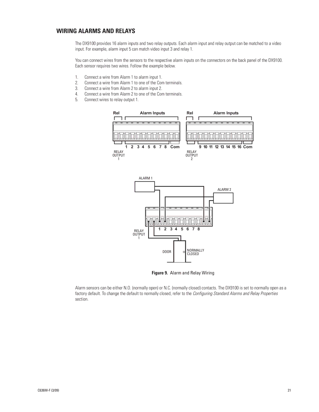
You can connect wires from the sensors to the respective alarm inputs on the connectors on the back panel of the DX9100. Each sensor requires two wires. Follow the example below.
1.Connect a wire from Alarm 1 to alarm input 1.
2.Connect a wire from Alarm 1 to one of the Com terminals.
3.Connect a wire from Alarm 2 to alarm input 2.
4.Connect a wire from Alarm 2 to one of the Com terminals.
5.Connect wires to relay output 1.
Rel | Alarm Inputs | Rel | Alarm Inputs |
| 1 2 3 4 5 6 7 8 Com |
| 9 10 11 12 13 14 15 16 Com |
RELAY |
| RELAY |
|
OUTPUT |
| OUTPUT |
|
1 |
| 2 |
|
| ALARM 1 |
|
|
RELAY
OUTPUT
1
|
|
|
|
|
|
| ALARM 2 |
1 | 2 | 3 | 4 | 5 | 6 | 7 | 8 |
DOOR
NORMALLY CLOSED
Figure 9. Alarm and Relay Wiring
Alarm sensors can be either N.O. (normally open) or N.C. (normally closed) contacts. The DX9100 is set to normally open as a factory default. To change the default to normally closed, refer to the Configuring Standard Alarms and Relay Properties section.
| 21 |