24 Rear Panel
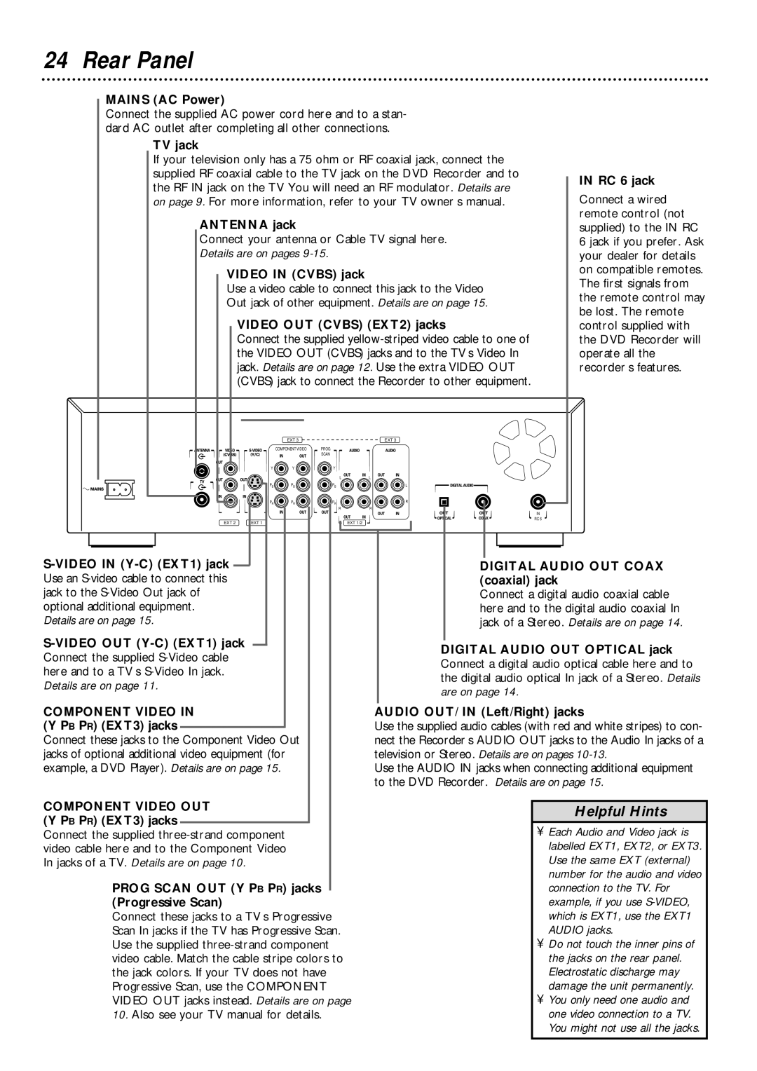
MAINS (AC Power)
Connect the supplied AC power cord here and to a stan- dard AC outlet after completing all other connections.
TV jack |
| |
If your television only has a 75 ohm or RF coaxial jack, connect the |
| |
supplied RF coaxial cable to the TV jack on the DVD Recorder and to | IN RC 6 jack | |
the RF IN jack on the TV You will need an RF modulator. Details are | ||
Connect a wired | ||
on page 9. For more information, refer to your TV owner’s manual. | ||
ANTENNA jack | remote control (not | |
supplied) to the IN RC | ||
Connect your antenna or Cable TV signal here. | 6 jack if you prefer. Ask | |
Details are on pages | your dealer for details | |
VIDEO IN (CVBS) jack | on compatible remotes. | |
The first signals from | ||
Use a video cable to connect this jack to the Video | ||
the remote control may | ||
Out jack of other equipment. Details are on page 15. | ||
be lost. The remote | ||
VIDEO OUT (CVBS) (EXT2) jacks | ||
control supplied with | ||
Connect the supplied | the DVD Recorder will | |
the VIDEO OUT (CVBS) jacks and to the TV’s Video In | operate all the | |
jack. Details are on page 12. Use the extra VIDEO OUT | recorder’s features. | |
(CVBS) jack to connect the Recorder to other equipment. |
|
| EXT 3 |
| EXT 3 |
| COMPONENT VIDEO | PROG |
|
|
| SCAN |
|
Y | Y | Y |
|
|
| L | L |
PB | PB | PB | L |
PR | PR | PR | R |
|
| R | R |
IN
|
|
|
|
| EXT 2 EXT 1 |
| EXT 1/2 |
|
|
|
|
| RC 6 |
|
|
| ||||||
|
|
|
|
|
|
|
|
|
|
|
|
|
|
| ||||||||
|
|
|
|
|
|
|
|
|
|
|
|
|
|
|
|
|
|
|
|
| ||
|
|
|
|
|
|
|
|
|
|
|
|
|
|
|
|
|
|
|
|
|
| |
|
|
|
|
|
|
|
|
|
| DIGITAL AUDIO OUT COAX | ||||||||||||
|
| |||||||||||||||||||||
Use an |
|
|
| (coaxial) jack | ||||||||||||||||||
jack to the |
|
|
| Connect a digital audio coaxial cable | ||||||||||||||||||
optional additional equipment. |
|
|
| here and to the digital audio coaxial In | ||||||||||||||||||
Details are on page 15. |
|
|
| jack of a Stereo. Details are on page 14. | ||||||||||||||||||
|
|
|
|
|
|
|
|
| DIGITAL AUDIO OUT OPTICAL jack | |||||||||||||
|
|
|
| |||||||||||||||||||
Connect the supplied |
|
|
| |||||||||||||||||||
|
|
| Connect a digital audio optical cable here and to | |||||||||||||||||||
here and to a TV’s |
|
|
| |||||||||||||||||||
|
|
| the digital audio optical In jack of a Stereo. Details | |||||||||||||||||||
Details are on page 11. |
|
|
| |||||||||||||||||||
|
|
| are on page 14. |
|
|
| ||||||||||||||||
|
|
|
|
|
|
|
|
|
|
|
|
|
|
|
|
|
|
| ||||
COMPONENT VIDEO IN |
|
|
| |||||||||||||||||||
| AUDIO OUT/ IN (Left/Right) jacks | |||||||||||||||||||||
(Y PB PR) (EXT3) jacks |
|
|
| Use the supplied audio cables (with red and white stripes) to con- | ||||||||||||||||||
|
| |||||||||||||||||||||
Connect these jacks to the Component Video Out |
| nect the Recorder’s AUDIO OUT jacks to the Audio In jacks of a | ||||||||||||||||||||
jacks of optional additional video equipment (for |
| television or Stereo. Details are on pages | ||||||||||||||||||||
example, a DVD Player). Details are on page 15. |
| Use the AUDIO IN jacks when connecting additional equipment | ||||||||||||||||||||
|
|
|
|
|
|
|
|
|
|
|
|
|
| to the DVD Recorder. Details are on page 15. | ||||||||
COMPONENT VIDEO OUT |
|
|
|
|
|
|
|
|
|
| ||||||||||||
|
|
|
|
|
|
|
|
| Helpful Hints | |||||||||||||
(Y PB PR) (EXT3) jacks |
|
|
|
|
|
|
|
|
|
|
|
|
| |||||||||
|
|
|
|
|
|
|
| • | Each Audio and Video jack is | |||||||||||||
Connect the supplied |
|
|
|
|
|
| ||||||||||||||||
video cable here and to the Component Video |
|
|
|
|
|
|
| labelled EXT1, EXT2, or EXT3. | ||||||||||||||
In jacks of a TV. Details are on page 10. |
|
|
|
|
|
|
| Use the same EXT (external) | ||||||||||||||
|
|
|
|
|
|
|
|
|
|
|
|
|
|
|
|
|
|
|
| number for the audio and video | ||
|
| PROG SCAN OUT (Y PB PR) jacks |
|
|
|
|
|
|
| connection to the TV. For | ||||||||||||
|
| (Progressive Scan) |
|
|
|
|
|
|
| example, if you use | ||||||||||||
|
| Connect these jacks to a TV’s Progressive |
|
|
|
|
|
|
| which is EXT1, use the EXT1 | ||||||||||||
|
| Scan In jacks if the TV has Progressive Scan. |
|
|
|
|
|
|
| AUDIO jacks. | ||||||||||||
|
| Use the supplied |
|
|
|
|
|
| • | Do not touch the inner pins of | ||||||||||||
|
| video cable. Match the cable stripe colors to |
|
|
|
|
|
|
| the jacks on the rear panel. | ||||||||||||
|
| the jack colors. If your TV does not have |
|
|
|
|
|
|
| Electrostatic discharge may | ||||||||||||
|
| Progressive Scan, use the COMPONENT |
|
|
|
|
|
|
| damage the unit permanently. | ||||||||||||
|
| VIDEO OUT jacks instead. Details are on page |
|
|
|
|
| • | You only need one audio and | |||||||||||||
|
| 10. Also see your TV manual for details. |
|
|
|
|
|
|
| one video connection to a TV. | ||||||||||||
|
|
|
|
|
|
|
|
|
|
|
|
|
|
|
|
|
|
|
| You might not use all the jacks. | ||
|
|
|
|
|
|
|
|
|
|
|
|
|
|
|
|
|
|
|
|
|
|
|