M1353-9000J
Page
Printing History
Page
Contents
Setting Time, Date, and Paper Speed
Preventive Maintenance Care and Cleaning
Modem Interface Module
Upgrade Key
Contents
Repair Strategy
Introduction
What to do
Next
Equipotential Terminal
Conventions and Symbols Used in this Guide
Claims for
Initial Inspection
Damage
Repacking
Fetal Monitor Parameters
Overview
Parameter
Major Keys and Parts at a Glance
Series 50 IP-2US1 socket
M1351A Single Ultrasound Model M1351A Dual Twins Model
Monitor Control and Display Panel
Monitor On/Off Light
M1353A Model 1. Monitor On/Off Light
Series 50 a
Accessories
M1351A
M1353A
Accessories
Options
Accessories Option Model
Accessories Option Model
Weight
Power Requirements
Dimensions
Monitor
Inputs
Displays
System
Signal Range
Frequency
Repetition Rate
Modem
Self-Test Facilities Combined Interface Module
Remote Event
Marker
Transducers and Cables
Noise
Input Impedance
Contact Potential Tolerance
Input Voltage Range
1290C option
IUP Quartz
J05
5µV/V/mmHg
IUP Pressure Transducer CPJ840J5
Fitting the Monitor to the Angle Mount
Fitting the Monitor to a Surface
Fitting the Monitor to the Wall Mount
Fitting the Monitor to a Wall
Fitting the Paper Take-Up Tray to the Monitor
Fitting the Paper Take-Up Tray
Carts Replacement Parts
Carts Specifications
Carts
Fitting the Barcode Reader Holder
1Configuration Tasks
Configuring the Monitor
Configuring the Monitor Using Pushbuttons
Menu Setting Options Default
2Configuration Options
Options NST Timer NST automatic Paper-Out-Alert
NST Timer Paper-Out-Alert
Configuring the Monitor Using a PC
Configuring the Monitor Using Barcodes
Service Program
Installing
Connecting PC to Monitor Loading Service Program Using
Main Menu
Example
Recorder
Service Menu
Reading the Options
Reading the Error Log
FIC
Service Function Menu Numbers and Error Log Functions
Configuring the Monitor Using a PC
Clearing the Error Log
Writing/Resetting the Serial Number and Setting the Options
To select an option
FHR Alerting Enable/Disable
5Error Log Messages
Error Log Messages
Reload the software
Error Log Messages
Time and Date
Setting Time, Date, and Paper Speed
Paper Speed Controls
Paper Speed
System Overview
Theory of Operation
Booting and Self Tests
Booting and Self Tests
M1351A M1353-66501 M1353-66511
Front End Board
M1353-66512
Apegblk5
Frontend Board
M1350-66517
Power Supply Board M1353-66502
CPU Board
CPU Board M1353-66503 and M1353-66513
M1353-66503
M1353-66513
CPU Board M1353-66503 and M1353-66513
Display Board M1350-66520
Recorder Interface Board M1353-66510
Interface Board
Interface Boards
Combined Interface Board M1353-66531E
Modem Interface Board M1353-69532
During startup
Interface Boards Theory of Operation
Service Tests
Service Philosophy
Performance Assurance Tests
Overview
Lswitched on subsequently
Monitor is switched on, Err
Quick Test
Test Pattern
Xxx is the number of the error message
US/US1
Signal Correct Monitor Response
Operator Error Messages
Operator Error Messages
FSpO2
Permanent Test
Troubleshooting Flowcharts
Troubleshooting Error
Error 500 General Failure
Connectors and LEDs
Troubleshooting Error 501, 511, 512, 516
Error 501, 511, 512, 516, 517 Front End Board
Connectors and LEDs
Error 502 Power Supply
Connectors and Fuses
Serial number and feature setting can only be written once
Error 503 and 513 CPU Board
Error 510 Recorder Board
Error 531 Combined Interface Board
10 Troubleshooting Error
Error 532 Modem Interface Board
11 Troubleshooting Error
Error 70 Modem Not Responding
12 Troubleshooting Error
Error 77 Modem Transmission Failure
13 Troubleshooting Error
Error 601 Paper Feed
14 Troubleshooting Error
Error 610 No Loudspeaker
15 Troubleshooting Error
Error 611 Loudspeaker
Ultrasound Parameter Test
16 Troubleshooting Ultrasound Parameter Test
Decg Parameter Test
17 Troubleshooting Direct ECG Parameter Test
Mecg Parameter Test
18 Troubleshooting Maternal ECG Parameter Test
Toco Parameter Test
19 Troubleshooting Toco Parameter Test
Maternal Nibp with the Dinamap 1846/8100 Monitor
Maternal Nibp with the Colin Model BP-8800 Monitor
Troubleshooting Flowcharts
Paper Sensing Test
23 Troubleshooting Recorder Paper Sensing
Cleaning the Monitor
Preventive Maintenance, Care and Cleaning
Maintenance
Regular Maintenance
Mechanical
Inspection
Testing Toco Transducers
Accessory Testing
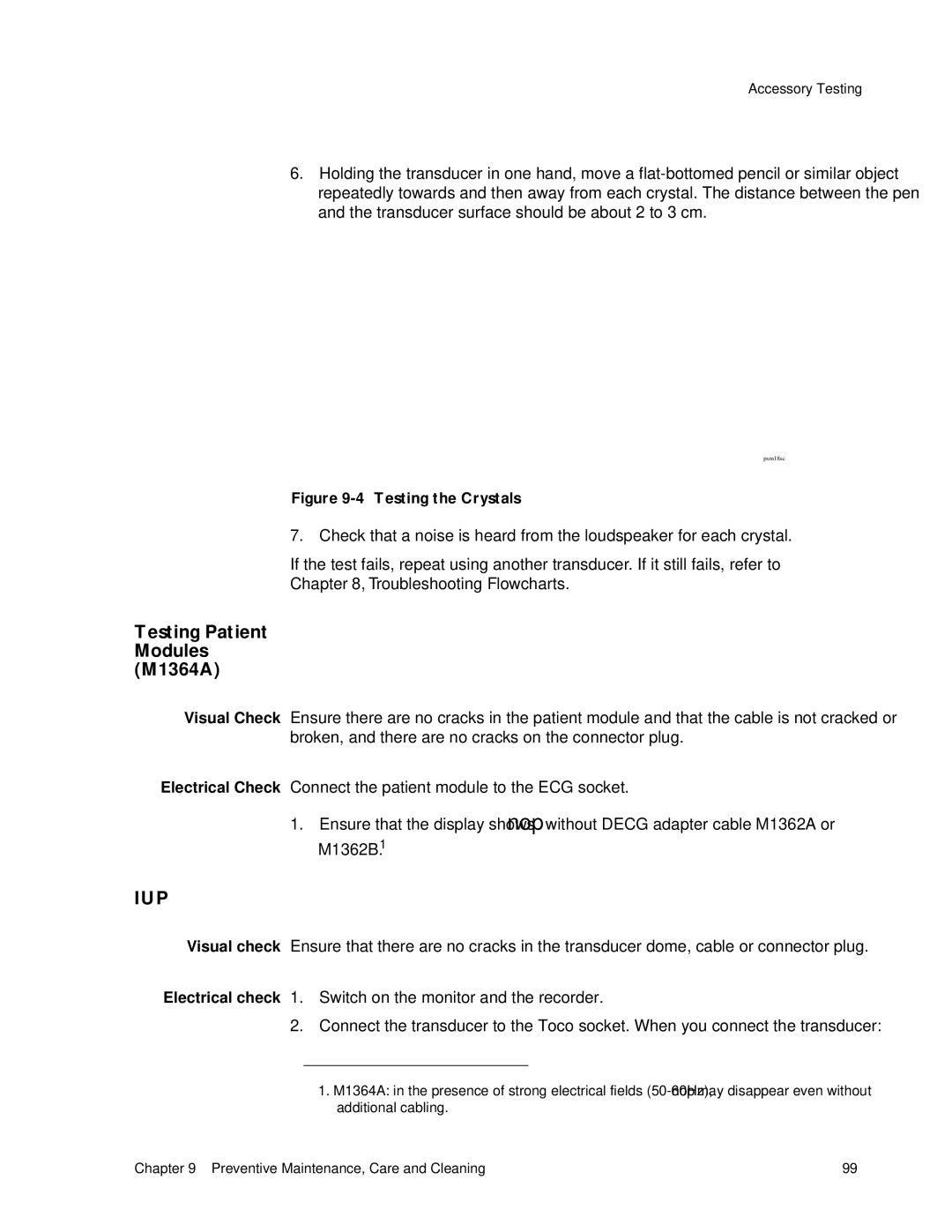
Testing an Ultrasound Transducer
Testing Ultrasound Transducers
IUP
Testing Patient Modules M1364A
Safety Test
Safety Testing
Procedures
Documentation included with those products
2M1351A and M1353A When to perform safety test blocks
When to Perform Safety Tests
Inspection Matrix
Test
M1351A/ M1353A Fetal Monitor Test and Inspection Matrix
Safety test according to IEC 60601-1 Clause
Safety Tests
Preventive Maintenance, Care and Cleaning 105
106 Preventive Maintenance, Care and Cleaning
Fitting the Combined Interface Module
Peripherals
2Connecting Peripheral Devices
Connecting Peripheral Devices
RS232 Serial Interface
Pin Signal Details
RS232 Interface Pin Connections
4Barcode Reader Pin Connections
Barcode Reader Pin Connections
5Interface Cable M1350-61609
Baudrate
Maternal Measurements on the FHR Trace
Startbit Parity
Databits Stopbits Cable
Paper Speed Minimum Time Interval
Nibp Monitor and Minimum Time Interval
Baudrate2400 Startbit Parity
Databits8 Stopbits1
DIP Switches and Settings
FSpO2 monitor DIP Switch Settings
Telemetry System Pin Connections
Telemetry System
Key
Obms and Odis Pin Connections
80235A OBMS, M1370A ODIS, and OB TraceVue
Pin Voltage Remarks
Pin 21 Output Voltage Values
Ordering Parts
Safety Test Requirements
Lists of Parts
Service Tools
Boards
Description Part Number
Boards Parts List
Monitor Parts
2Monitor Parts Diagram 1
Description Part Number Qty Darker color New color
Monitor Parts List
Replacement Part List
5Changes to the Recorder
Monitor Housings Color Changes
Monitor Housing Color
Miscellaneous Parts List
Description Part Number Qty
Toco Transducer Blue,M1355A
Toco Transducer Parts List
Ultrasound Transducer M1356A Blue
Ultrasound Transducer Blue,M1356A
Decg Transducer M1357A
Decg Transducer Parts List
Cable Color Old
9MECG Transducer M1359A
Mecg Transducer Parts List
Toco Transducer Brown
11Toco Transducer Parts List
Pin Cable Color Strain
12Toco Transducer Cable Connections
Ultrasound Transducer Brown
13Toco Transducer Parts List
Pin Cable Color
15 Parts List
Parts List
Patient Module M1364A
Description Exchange Part Part Number Qty
Fuses
Batteries
11Removing the Top Cover
Top Cover
Carry out the Parameter Test see
16Fuse Part Numbers
Power Supply Board
All Fuses
CPU Board
Modem Interface Module
Combined Interface Module
Chassis
On/Off Switch
12Refitting the Recorder Board
Recorder Board
Display Board
Switch Board
Loudspeaker
Transformer
Remove the recorder chassis
Drawer Assembly
Figure -5, Changes to the Recorder on
Thermal Printhead
152 Replacing Parts
This screw position is reserved
Recorder Sensing Assembly
Stepper Motor
Fitting the Modem Interface Module
Modem Interface Module
15 Connecting Peripheral Devices
Barcode Reader
DCD
Page
Setting Receiver Phone Number Patient Phone Patient ID
Memory
Clearing
162
Pcmcia Card Modem
Compatibility
Using Modem Setup Barcodes
Initialization
List of Parts
Troubleshooting and Error Messages
Connection
Telephone
Appendix a Modem Interface Module 167
Service Barcodes
Modem Setup Barcodes
18Service Barcodes
@ * %
170
Patient Safety
Safety Information
M1351A
Environment
M1353A
Spillage
Characteristics
Electromagnetic Compatibility
System
Avoiding
Can be done to mitigate the problem
Interference
Upgrade Procedure
Upgrade Key
Upgrade Procedure
Index
178 Index
Index 179