Pressure Systems, Inc. | |
|
|
The NetScanner™ System is a comprehensive, distributed data acquisition system centered around PSI’s proven Intelligent Pressure Scanner technology. The rackmount configuration of this system is comprised of Model
(8)Model 9816 Rackmount Intelligent Pressure Scanners networked via the Ethernet interface. The
Each Model 9816 Rackmount Intelligent Pressure Scanner module integrates sixteen (16) silicon piezoresistive pressure sensors and a unique patented calibration manifold with an onboard
the Ethernet interface. Each pressure sensor is packaged with an integral EEPROM for storage of calibration data unique to the sensor. Integrating the EEPROM within the sensor enables simple ‘plug and play’ field replacement of transducers with automatic uploading of sensor data during system
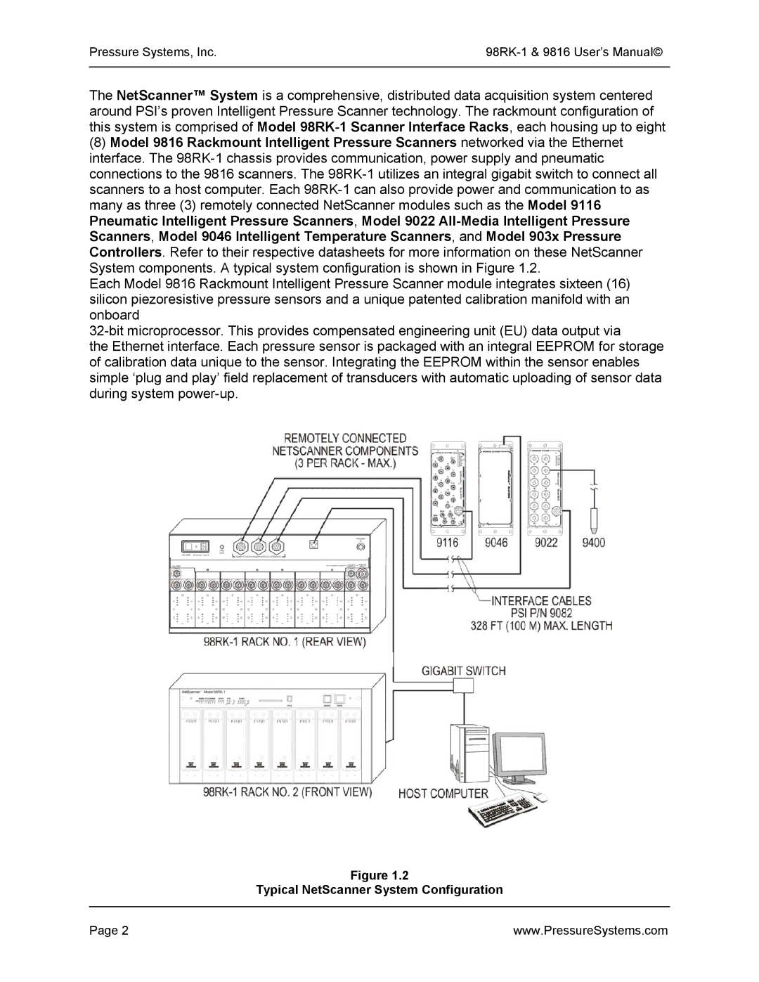
Figure 1.2
Typical NetScanner System Configuration
Page 2 | www.PressureSystems.com |