RIC-E1
Order from Cutter Networks Ph727-398-5252/Fax727-397-9610
RIC-E1
International Headquarters RAD Data Communications Inc
Limited Warranty
General Safety Instructions
Please observe the following precautions
Connection of AC Mains
General Safety Practices
Connection of DC Mains
Ports Safety Status
Isdn
Electromagnetic Compatibility EMC
Canadian Emission Requirements
Safety
Manufacturers Name Manufacturers Address
Product Names
Supplementary Information
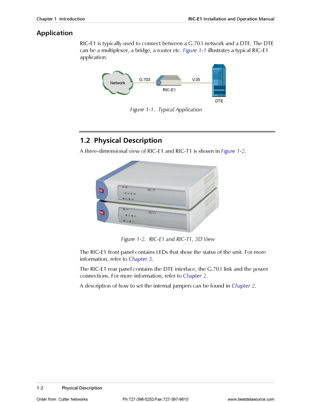
Installing RIC-E1
Setting the Internal Jumpers
Jumper Description Values Default Setting
Quick Start Guide
Operating RIC-E1
Connecting the Cables
To connect cables
Contents
List of Figures
Power Supply
Chapter Introduction
Overview
Versions
Physical Description
Application
Functional Block Diagram
Diagnostics
Functional Description
Timing Reference
Technical Specifications
Receive, derived from the received signal
Derived from three alternative sources
Internal oscillator
Diagnostics
Power
Physical
Environment
Technical Specifications
Package Contents
Chapter Installation and Setup
Site Requirements and Prerequisites
Configuring RIC-E1
Setting the Jumpers
To install RIC-E1
To set the jumpers
RIC-E1 Jumper Locations RIC-E1 Jumper Settings
Connecting the Interfaces
Connecting the E1 Line
Selecting the Impedance
Closing the RIC-E1 Case
Connecting the Power
Connecting the DTE
Connecting the AC Power
Connecting the DC Power
Installation and Setup
Chapter Operation
Front Panel Indicators
Designation Color Function
Operating Instructions
Turning On
Operating RIC-E1
Turning Off
Performing Local Analog Loopback
Chapter Troubleshooting Diagnostics
Activating Local Analog Loopback
Troubleshooting
RIC-E1 Troubleshooting
Deactivating Local Analog Loopback
To activate the local analog loopback from RIC-E1/R
Technical Support
Technical Support
Line Connector
DTE Connector
Chapter RIC-E1/R Card
ASM-MN-214 Card Cage
ASM-MN-214 Rear Panel
Power Supply
Power Supply with Redundancy
AC Supply
DC Supply
RIC-E1/R Front Panel
IR-ETH or IR-ETH
ASM-MN-214 Front Panel
Setting Internal Jumpers and Switches
Installing the RIC-E1/R Card
RIC-E1/R PCB Layout RIC-E1/R Jumper Settings
Installing RIC-E1/R into the ASM-MN-214 Card Cage
To install the RIC-E1/R card in the ASM-MN-214 card cage
RIC-E1/R Card
Appendix a Interface Connector Wiring
V.35, X.21 and RS-530 Interface Connectors
V.36 Interface Connector
Signal Function 36, 37-Pin RS-530, 25-pin Circuit
Line Interface Connector
Table A-3. RJ-45 Line Interface Connector, Pin Assignment
Signal Function 36, 37-pin RS-530, 25-pin Pin Circuit
Pin Function
Appendix a Interface Connector Wiring
Appendix B IR-ETH Interface Module
Contents
Introduction
IR-ETH Options
Standalone RIC-E1
RIC-E1/R Card
Table B-1. RJ-45 Pinout
Figure B-3. RIC-E1/R with IR-ETH
Installation and Operation
LED Indicators
Setting the DIP Switch
Table B-2. DIP Switch Settings
Connecting the LAN
Table B-4. IR-ETH LED Indicators, RIC-E1/R
Link
ACT
Appendix C IR-ETH/V Interface Module
IR-ETH/V Options
RIC-E1
For example, MDI in OFF position, MDI is enabled
Mbps full duplex, 285 ∝s
Throughput
Data 00, 01, 02, …
Setting the DIP Switches
Table C-2. DIP SW1 Switch Settings
Moved by the user Table C-3. DIP Switch SW2 Settings
Section Name Description Possible Settings Factory Setting
Backpressure and Flow Control
Table C-4. IR-ETH/V LED Indicators
Color Function
Appendix D IR-IP Interface Module
Introduction
Appendix D IR-IP Interface Module
Connector 10BaseT Shielded RJ-45
Standard Ieee 802.3/Ethernet Data Rate
Protocols
Frame Relay RFC
RIC-E1/ IP
IR-IP LEDs
IR-IP Controls
Table D-1. IR-IP LEDs Functions Standalone RIC-E1
Table D-2. IR-IP LEDs Functions RIC-E1/R Card
Control Function Values Default Setting
IR-IP Management Subsystem, General
Table D-3. IR-IP Controls
Table D-4 RJ-45 Pinout
Accessing the IR-IP Management Subsystem
Default IP Communication Parameters
Performing Preliminary Configuration
Rescue Configuration
Outline of Preliminary Configuration
To allow the IR-IP configuration
Connecting the Telnet Host
Preliminary Telnet Host Configuration
Assigning the Router LAN Interface Address
IP Learning Mechanism
To configure the IP router LAN address
To view and edit the ARP table contents
Assigning a LAN IP Address to a New IR-IP
Changing the LAN IP Address of a Configured IR-IP
After RIC-E1 is turned on, the ERR indicator does not light
What to Do If
No ping replies from IR-IP
IR-IP Management Utility
General Operating Procedures
Starting a Management Utility
To access the Quick Setup menu
Quick Setup Menu
Menu Structure of Management Utility
Default Gateway
LAN IP Address
LAN IP Mask
WAN IP Address
Read Protocol from DIP Switches
Operation with Default Gateway
To configure the IR-IP as a Dhcp relay
Dhcp Relay
Management Access Menu
Telnet Password
To access the Management Access menu
Protocol
Advanced Setup Menu
Telnet Inactivity Timeout
To access the Advanced Setup menu
To access the Device Identification menu
To access the Interface Parameters menu
Interface Parameters Menu
Device Name
Contact Person
WAN Protocol Parameters Frame Relay Protocol Menu
Authentication Protocol
WAN Protocol Parameters PPP Protocol
Header and Control Field Compression
Protocol Field Compression
Multicast IP
Multicast Forwarding
Figure D-17. Multicast IP Menu
Device Control
To access the Device Control menu
Static Groups
Viewing Error Log Screen
New Software Download Menu
Erasing Configuration
Resets Menu
Resetting the Device
Resetting the LAN Interface
Configuration and Connection
To access the View menu
To access the Configuration and Connection screen
View Menu
To access the ARP Tables screen
ARP Tables
To access the Multicast Groups Table screen
To access the Statistics menu
Multicast Groups Table Screen
Displaying Statistics
Diagnostic Tools Ping Terminal
To access the Diagnostic Tools menu
Using the Ping Function
To ping a host
Erasing User’s Configuration
To erase the user’s configuration
Erasing IR-IP Software
Desired positions, and then turn the RIC-E1 on again
Erasing Application Software
Downloading New Software
To erase the application software
Case, it is recommended to turn RIC-E1 off and then back on
Appendix D IR-IP Interface Module
Appendix E IR-X.21B Interface Module
Rear Panel
EXT Clock Mode
Selecting the IR-X.21B Timing
IR-X.21B
INT/LBT Clock Mode
Buffer
Appendix E IR-X.21B Interface Module
Impedance, 2-4Indicators
Index
IP-IR
IR-ETH
LED
IR-IP
Requirements, 2-1RIC-E1/R Card
Customer Response Form
Excellent Good Fair Poor Very Poor
Error Report
Order from Cutter Networks Ph727-398-5252/Fax727-397-9610
International Headquarters