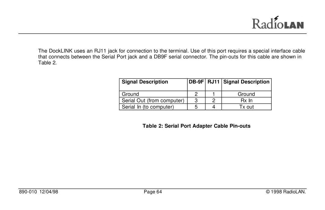
Wireless Local Area Network DockLINK User Guide
890-010 12/04/98
Notices
Low Power Communication Device Transmitter
FCCID MCIPUNIIT
FCC Rule Parts
Frequency MHz
Disclaimer
Trademark Disclosures
Manual Conventions
SMALL CAPITAL LETTERS describe Screen Names or Screen Tab Names
Table of Contents
Using the DockLINK Manager
Table of Contents
Quick Installation Steps
Recording Important System Information
Managing the DockLINK Locally
Troubleshooting
Appendix A Indicators, Switches, and Connectors
Serial Port connector
Appendix B Technical Specifications
Introduction
Figure 1 The DockLINK and Radio Unit
Transform a 10BaseT Network Node into a Wireless Network Station
Adding Security to the Wireless Network Station
Designed for Simplicity
Local Management
System Requirements
Browser Requirements
Quick Installation Steps
Figure 3 Quick Installation Steps
To Test the Antenna Placement
Designing Your System
Testing the Data Range
Figure 4 Testing Data Range
Installing the DockLINK
Figure 5 Network Requirements
Locating the Radio Unit
Good Bad
Do this
Do not do this
Connecting the DockLINK
Figure 7 Connecting the DockLINK
Figure 8 Setting the MDI/MDI-X Switch
Initial IP Address Setup
Figure 9 Quick Configuration
Connect the DockLINK
2. Connect the Radio Unit to the DockLINK
Optional Configuration Disk
Using the DockLINK Manager
The DockLINK Manager
Accessing the DockLINK with the Browser
Logging Onto the DockLINK Manager
PasswordBlank
User Name
Enter Password
Product ID
Enter User Name
DockLINK Manager Layout
Figure 11 The Main Menu
Figure 12 The Main Page
Discovering Wireless Nodes Within the DockLINK’s Data Range
Figure 13 Node Discovery Network Information Page Station List Tab
Station List
Name
Address
Type
Link
Table 1 Link Quality Ratings
Score
Color
Connectivity
Name
Link
Figure 14 Node Discovery Network Information Page Connectivity Tab
Setting Up Security Features
The User Password and Retype Password Fields
User Logon Name Fields
Use Default
IP Parameters
Reload
Default Gateway IP Address
IP Address
Subnet Mask
Disabled Radio Button
DHCP Operation Modes
Acquire system IP Only Radio Button
Download System Software Only Radio Button
Download System Software and Save It Radio Button
DHCP Server IP Address
Setting the DockLINK’s Mode of Operation
Dock Mode
Securing the DockLINK with Data Encryption
Data Encryption Enabled Check Box
This selection enables or disables Data Encryption on
Figure 18 Data Encryption Page
Setting up10BaseT Port Parameters
Figure 19 10BaseT Port Parameters Page
MAC Address Filter
Edit Button
Block IP Packets
Block NetBIOS Packets
Block IPX Packets
Block NetBEUI Packets
Radio Port Parameters
Port Name
Unchecked Disables MAC Address filtering
Subnet ID
MAC Address Filter
Edit
Block IP Packets
Block IPX Packets
890-010 12/04/98
Page
Block NetBIOS Packets
Block NetBEUI Packets
890-010 12/04/98
Page
Setting the Baud Rate for the Local Port
Figure 21 The Console Parameters Page
Managing Packet Flow through the DockLINK
Figure 22 MAC Address Table
MAC Address
Mask Bytes
Source/Dest
Accept/Reject
Adding MAC Filters
Modifying MAC Filters
Deleting MAC Filters
Interrogating DockLINK for Performance Information
Checking 10BaseT Port Statistics
Total Packets Transmitted
Figure 23 10BaseT Port Statistics Page
Total Error Packets
CRC Error Packets
Collision Error Packets
Total Packets Received
Pressing the button resets all counters on this page to
Checking Radio Port Statistics
The page has two major sections ∙ Packet Transmission
∙ Packet Reception
The Packet Transmission stores information about packets that are sent from the DockLINK to wireless stations on the network
Packet Transmission
Total Packets Transmitted
Average Transmit Rate Packets/Sec
The Packet Reception indicates the DockLINK’s ability to receive packets from distant wireless stations
Packet Reception
Total Packets Received
Average Receive Rate Packets/Sec
Upgrading System Software
∙ Upgrade from file radio button
∙ Upgrade TFTP server radio button not used ∙ File to Upload field
Upgrade from File
∙ Browse button ∙ Upload button
Upgrading from a TFTP Server
Address field. Do not use this selection with DockLINK
Set TFTP Server IP Address
System Software File Name
Saving or Rejecting Configuration Setting Changes
∙ Save All Changes and Reset radio button
∙ Reload Last Saved Configuration radio button
∙ Reset Configuration to Factory Default radio button
Reload Last Saved Configuration Radio Button
Reset Configuration to Factory Default Radio Button
Resetting the DockLINK
Figure 28 Reset Page
Testing DockLINK Connectivity to the Wireless Network
Setting the Frames to Send
Figure 29 Ping Radio Port Page
Setting the Frame Size
Setting the Address
Frames Sent
Frames Acked
Success %
Avg Retrans
Start Button
Stop Button
Recording Important System Information
Product Name
System Name
System Contact
Default Gateway
Radio Port MAC Address
10BaseT Port MAC Address
Subnet ID
Boot Software Version
System Software Version
System Software File Name
Hardware Revision
Viewing the System Log
Error No
Error Message
Task
Managing the DockLINK Locally
Figure 33 Connecting the VT-100 Terminal to the DockLINK
Signal Description
Signal Description
DB-9F
RJ11
DockLINK Local Management
Configuring the DockLINK for use in the Dock Mode
Prompt
For more information, see
Station Name
Logging onto the DockLINK Configuration Screen
Serial Number
The Enter User Name field is an entry field where you enter your user name to gain access to the configuration and diagnostic screens. Only entries matching those programmed into the SYSTEM CONFIGURATION ACCESS S ECURITY MENU are allowed access to the program
Enter Password
Enter User Name
Using the Main Menu
System Features
Node Discovery
Figure 35 The Main Menu
System Configuration
Diagnostics
System Statistics
System Status
Working with the System Configuration Menu
Administration Parameters
Figure 38 System Configuration Menu
IP Parameters
Port Parameters
Figure 39 Port Parameters Menus
SNMP Parameters
Access Security
Configuration Changes
System Operation Mode
CONFIGURATION - ACCESS SECURITY MENU on page 74 for more information
Configuration Manager Menu Items
User Password
Menu Name
Menu Item
Default Gateway IP
Menu Name
Menu Item
Refer to
DHCP Operation Mode
Dock Mode
Data Encryption Mode
Menu Name
Enable Encryption
Menu Name
Menu Item
Refer to
Menu Name
Menu Item
Refer to
Port Name
Menu Name
Menu Item
Refer to
Source or Destination
Download Mode
Menu Name
Menu Item
Refer to
Save All Configuration
Menu Name
Menu Item
Refer to
Configurations
Menu Name
Menu Item
Refer to
Menu Name
Menu Item
Refer to
Perform Ping
Menu Name
Menu Item
Refer to
System Information
Troubleshooting
Indicators
Problem No traffic passed
Problem Radio Range seems less than it should be
Access Point Agent Client Station
Glossary
DHCP Server DNS Domain Gateway
IP Address MAC Address Manager MIB Node
Packets
Ping
Routing
Subnet Mask TCP/IP
Appendix A Indicators, Switches, and Connectors
Indicators
Power LED
Fault LED
MDI/MDI-X switch
Status LEDs
IO Connectors
10BaseT connector
Serial Port connector
Signal Description
Signal Description
DB-9F
Appendix B Technical Specifications
Electrical Specifications
Network Protocol
Standards Support
Physical Specifications
Environmental Specifications
Dimensions
Weight
Safety Agency Approvals
Electromagnetic Emissions
Meets requirement of FCC Part 15, subparts A and B, Class A
EN55 022 CISPR 221985, Class A
Getting Technical Support
Index
Page
Page
Page
IP ASSIGN Utility · 14, 15 location guidelines · 7 prerequisites ·
Page
Page
Page
setting up · 25 serial devices ·
890-010 12/04/98
Page
Page
wireless networks optimal spacing ·
wireless nodes · 21 wireless stations · adding ·
protecting from unauthorized users · 3 setting up · 7
testing data range ·
RadioLAN
455 De Guigne Drive Sunnyvale, CA Phone 408 Fax 408