3.11 Installing and Adjusting the Anamorphic Lens
If you are installing an
It is extremely important that the primary lens is properly
Note adjusted before you install the anamorphic lens. Ensure that the image from the primary lens is perfectly centered on the screen.
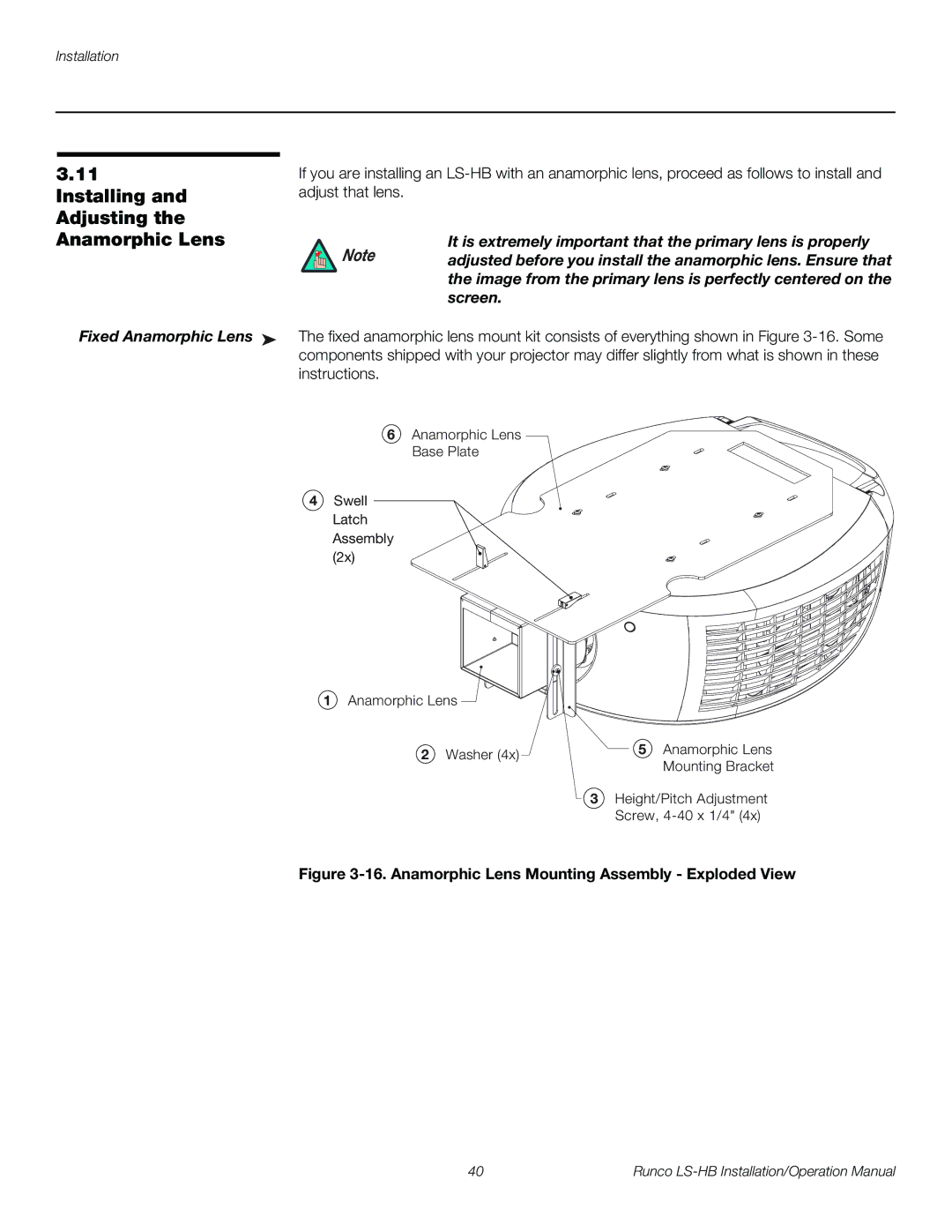
Fixed Anamorphic Lens ➤ The fixed anamorphic lens mount kit consists of everything shown in Figure
6Anamorphic Lens Base Plate
4Swell
Latch Assembly (2x)
1Anamorphic Lens
2 Washer (4x) | 5 Anamorphic Lens | |
Mounting Bracket | ||
|
3 Height/Pitch Adjustment
Screw,
Figure 3-16. Anamorphic Lens Mounting Assembly - Exploded View
40 | Runco |