Maintenance and Troubleshooting
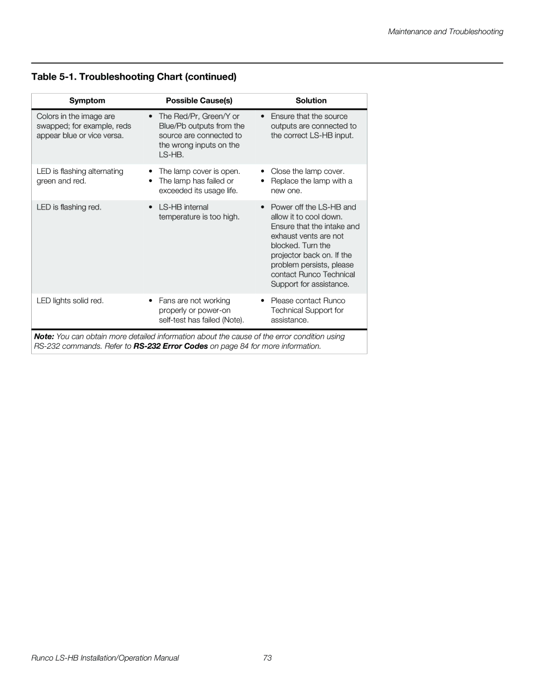
Table 5-1. Troubleshooting Chart (continued)
Symptom | Possible Cause(s) | Solution |
|
|
|
Colors in the image are | • The Red/Pr, Green/Y or | • Ensure that the source |
swapped; for example, reds | Blue/Pb outputs from the | outputs are connected to |
appear blue or vice versa. | source are connected to | the correct |
| the wrong inputs on the |
|
|
|
|
|
|
|
LED is flashing alternating | • The lamp cover is open. | • Close the lamp cover. |
green and red. | • The lamp has failed or | • Replace the lamp with a |
| exceeded its usage life. | new one. |
|
|
|
LED is flashing red. | • | • Power off the |
| temperature is too high. | allow it to cool down. |
|
| Ensure that the intake and |
|
| exhaust vents are not |
|
| blocked. Turn the |
|
| projector back on. If the |
|
| problem persists, please |
|
| contact Runco Technical |
|
| Support for assistance. |
|
|
|
LED lights solid red. | • Fans are not working | • Please contact Runco |
| properly or | Technical Support for |
| assistance. | |
| ||
Note: You can obtain more detailed information about the cause of the error condition using | ||
|
|
|
Runco | 73 |