Chapter 1: Getting started
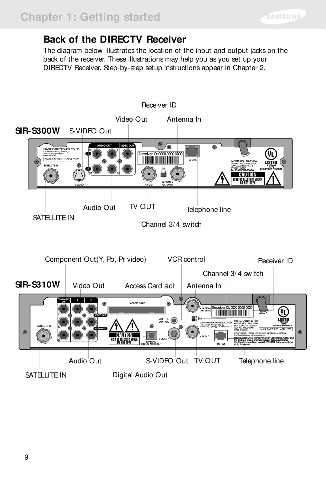
Back of the DIRECTV Receiver
The diagram below illustrates the location of the input and output jacks on the back of the receiver. These illustrations may help you as you set up your DIRECTV Receiver.
Receiver ID
Video Out
Antenna In
|
|
|
|
|
|
|
|
|
|
|
|
|
|
|
|
|
|
|
|
|
|
|
|
|
|
|
|
|
|
|
|
|
|
|
|
|
|
|
|
|
|
|
|
|
|
|
|
|
|
|
|
|
|
|
|
|
|
|
|
|
|
|
|
|
|
|
|
|
|
|
|
|
|
|
|
|
|
|
|
|
|
|
|
|
|
|
|
|
|
|
|
|
|
|
|
|
|
|
|
|
|
|
|
|
|
|
|
|
|
|
|
|
|
|
|
|
Audio Out TV OUT |
|
| ||||||||||
Telephone line | ||||||||||||
SATELLITE IN
Channel 3/4 switch
Component Out(Y, Pb, Pr video) | VCR control | Receiver ID |
Video Out |
|
| Access Card slot | ||||||
|
|
|
|
|
|
|
|
|
|
|
|
|
|
|
|
|
|
|
|
|
|
|
|
|
|
|
|
|
|
|
|
|
|
|
|
|
|
|
|
|
|
|
|
|
|
|
|
|
|
Channel 3/4 switch
Antenna In
|
|
|
|
|
|
|
|
|
|
|
|
|
|
|
|
|
|
|
|
|
|
|
|
|
|
|
|
|
|
|
|
|
| Audio |
| Out |
| Telephone line | |||||
|
| |||||||||
|
|
|
|
|
|
|
|
|
|
|
SATELLITE IN |
|
|
|
|
|
| ||||
Digital Audio Out |
|
|
| |||||||
9
