Printer
Sato America, Inc
Table of Contents
Buffer Clear
Printer Configuration
Maintenance
Troubleshooting
Introduction
Personal Injury
About this Manual
Primary Components
General Description
LCD Display
Control Features
Technical Data
Power
Physical Characteristics
Command
Environmental
Media
Sensing
Ribbon
Regulatory
Character Font Capabilities
Barcode Capabilties
Installation
Unpacking & Parts Identification
Unpacking & Parts Identification
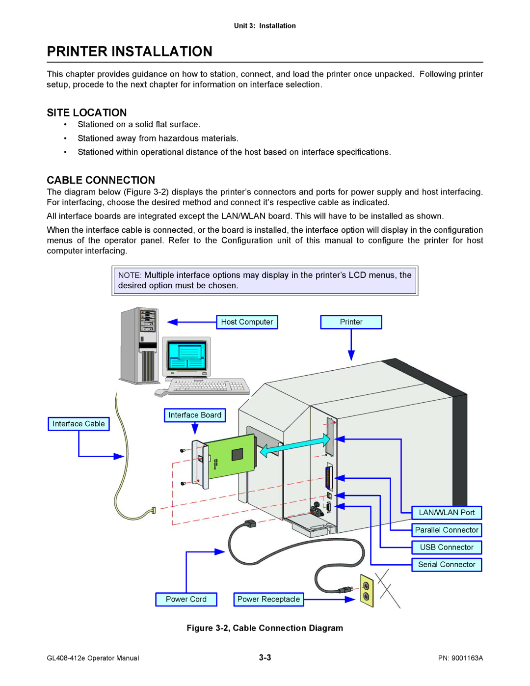
Cable Connection
Printer Installation
Site Location
Media & Ribbon Loading
Media Selection
3b, Fan-fold Media Loading
Operational Mode Selection
Label Print Direction
RS232C HIGH-SPEED Serial Interface
Interface Specifications
Interface Selection
Signal Ground
Signal Signal Definition
Printing e.g., ribbon out, label out
Buffer reaches the buffer near-full level
IEEE1284 Parallel Interface
Specifications
PIN Assignments Signal Direction
Local Area Network LAN Ethernet
Software Specifications
Universal Serial BUS USB
LED Indicator Status
802.11G Wireless
Network Port Link LED Off To 50% weak
Wireless LAN Signal Strength
50 to 75% medium
75 to 100% strong
ALL Interfaces
Interface Signals
Cable Requirements DB9 Host Direction Printer
Receive Buffer Control
Unit 3 Installation
Unit 3 Installation
External Signal
+5V +24V
+5V Machine Error Output
High high impedance, Low -15mA or more
Reprinting
Input Signal Wave Form Start Printing
Machine Error
Output Signal Wave Form Basic Operation
Paper END
Ribbon END
14, Operation Mode Flow Chart
Flash Memory Card
Accessories Installation
Interface Installation
Printer Configuration
Unit 4 Printer Configuration
User Mode
Configuration Modes
Line
Configuration Mode
3a, Advanced Mode
Advanced Mode
3b, Advanced Mode
Enter
Serial Interface Mode
Parallel Interface Mode
Parallel Interface Mode
Centronics
Centronics Interface Mode
USB Interface Mode
Universal Serial BUS USB Interface Mode
Interface Mode
Local Area Network LAN Interface Mode
Wlan Address
Wireless Local Area Network Wlan Interface Mode
Emulation
PGL Emulation Mode
ZGL
ZGL Emulation Mode
DGL
DGL Emulation Mode
TGL
TGL Emulation Mode
IGL
IGL Emulation Mode
15, Diagnostics Mode
Diagnostics Mode
16, Printer Management Mode
Printer Management Mode
Buffer Clear
Display Intensity Adjustment
Misc Quick Menus
KEY LOCK/UNLOCK
Soft Reset
Menu Description
User Mode Table
Menu Definition Tables
Addition to its size it a determinant
From the printer’s center frame
Material or gap
Or hole to the leading edge of the next notch or hole
Adjusted by this menu between -100and +100
No Change factory default
Presented in the UPC/EAN barcodes
Readable data is not present
Enable Will reprint a label affected by an error condition
Using gap or black mark media
Enable is the factory default
Activity
Configuration Mode Table
Powered off
Is the menu selection screen for the Configuration Mode
Exisitng configuration has first been deleted
Factory default is
Factory default is Current
Is a sub-menu of the configuration print feature
Disable factory default. Will overwrite
Enable will not overwrite
Advanced Mode Table
Menu options
Assembly installed
Permits selection of the media handling method desired
Label over the tear bar for removal
Current configuration menu
Leading edge of the eye-mark indicator black mark
Handling method
But only supports label lengths 2.50 inches or longer
Permits entry into the Power Saver TIme sub-menus
Each label. The factory default is Print Profile
Disable the power saver feature will not function
Factory default is English
Enable or disable. Disable is the factory default
Serial is the factory default
PPI/ZGL to send the status back to the host
To/from flash memory or Ram
Is the sub-menu of the Auto Locking feature
Auto Locking sub-menu to be enabled or disabled as desired
Extended Memory Card Flash File System
Being overwritten by disabling the overwrite function
Again. Press the Function key to exit the Advanced Mode
Is the sub-menu of the Set Lock Key feature
Range is 0 to 512, and the factory default is
Is 0 to 512, and the factory default is
Enable increases the point height by approximately 10%
512, and the factory default is
Allowable range is 0 to 20, the factory default is
Continually display
Factory default is 75 for eye-mark sensing
Factory default is 171 with a range of 000 to
Factory default is 150 for eye-mark sensing
Within the current configuration menu
To read reference indicators
After a Printhead Open fault
Factory default is 0.12 inches
Peel-Off Media Handling mode
Serial Interface Mode Table
No factory default. Will not be deleted
Is the menu selection screen for the Interfaces Mode
Deleted when the printer’s power is turned off
Deleted
Follow
Factory default is None
Into the applicable menus
Computer. The options are Odd, Even, Mark, Sense, or None
Kbytes in 1 kbyte increments
Transmission
False never asserts the DTR signal
True factory default. Continuaously asserts the DTR signal
On-Line- asserts the DTR signal when the printer is online
On-Line- asserts the RTS signal when the printer is online
Parallel Interface Mode Table
Will follow
Disable the option
Disable is not used
To 16 Kbytes in 1 kbyte increments
Busy for too long
Printer is offline until the printer’s buffer is full
Centronics Interface Mode Table
Menus will follow
Signal is true
Which interpret the 8th data bit line as a PI signal
Option
Codes
Universal Serial BUS USB Interface Mode Table
Is the menu selection screen for the Interfaces Mode
Local Area Network LAN Interface Mode Table
Interfaces
Ethernet interface is not in use
Display menu item Timeout
Disable will not recognize
Enable factory default. Will recognize
Match the host computer setting
Allowable range is 0 to 65535, and the factory default is
Defaults for the SEG1 through SEG4 are 000, 000, 000,
Factory defaults for SEG1 through SEG4 are 000, 000, 000,
Factory default is Disable
Read only
Ethernet Port Ethernet Setting Wlan Address Wlan Setting
Ethernet
Initialization, the LCD displays E-NET Ready
Cannot be changed
Dynamic and read only
Auto-negociate- factory default. Automatically selects
These characters may be alphanumeric, symbols, or spaces
Access Point in infrastructure mode
Two peers must be specific to one manufacturer
Enable does not conform to European standards
Disable factory default. Conforms to European standards
Open factory default. Provides open authentification
Allows all four WEP keys to be simultaneously reset
Permits entry into the Emulation Mode
PGL Emulation Mode Table
Is the menu selection screen for the Emulation Mode
Will contain a list of emulation options available
Command
Provides access to the desired character set
Disable factory default. Will print in upper and lowercase
Enable will print text only in uppercase
Allowable range is 1 to 255, and the factory default is
Sfcc denotes the following data is a PGL command
Form Adjust
Create command plus the Var Form Adjust menu
Feature is initialized in the Normal mode
On the PGL Normal menu setting
Quite mode
Command. This setting is IGP-100 compatible
Normal factory default. Normal scaling
Scalable factory default. Uses scalable fonts
Disable factory default. No effect
Command is presented
Is reported as an error
Factory default is 0 dots
Status factory default. Select Stcc Status command
Cancel select Stcc Cancel command
ZGL Emulation Mode Table
PPI supports text printing using the LP+ emulation
Allows selection of control instructions command prefix
Command will immediately take effect
Factory default is HS Command
Determines the method of setting the Label Length
Setting and select that configuration as the Power-Up
Setup or Media Control menu
Selects the current setting associated wit the JM command
DGL Emulation Mode Table
Enable feedback characters are sent to the host
Is the menu selection screen for the Emualtion Mode
Specifed in the command
Underlying emulation
To this setting after the current label format is finished
Imperial factory default. American Standard values
Possible. Commands containing errors will be ignored
Can be fine adjusted by this menu
TGL Emulation Mode Table
Enable the zero character is overlayed with a slash
Determines where and how errors will be displayed
Ignored
No all data is is passed to the LP+ emulation
Factory default is 0xB0
Euro symbol can be set to any value between 0x20 and 0xFF
Ignores the following comands or command parameters
Factory default is Process
IGL Emulation Mode Table
Advanced 5mil factory default. Standard for 203 dpi
Allows the selection of the printer’s print resolution
Head is installed, the mode will always be Advanced 3.3mil
Factory default is US Ascii
Preceding commands have been processed
To the immediate commands
Disable factory default. Will not send status message
Enable will send status message
Calculations can be fine adjusted
Override operator panel settings
Allowable range is -100to +100 with a factory default
Resolution of the printer running IGL
Is the menu selection screen for the Diagnostics Mode
Permits entry into the Diagnostics Mode
Used for printing. The LCD will reflect the new setting
Incoming print job regardless of different command settings
Diagnostics Mode Table
Dist, Head On Time to zero
This value is set to zero at the factory following testing
Following testing
Printer Management Mode Table
Printer Management Mode Table
Disable factory default. Is not active
This menu disables the serial port
Enable is active
Power-up. Resets the modem configuration to
Quick Menus Tables 4-17 Through
Troubleshooting
Display Explanation Solution
Error Signal Troubleshooting
Delete and optimize files
Printer encountered an error trying to
Reboot the printer
Mem Adjust size in the Printer Setup menu
Flash memory
Engine control software failure
Rotates Problem writing to flash memory
Different fault message will apear
Setup menu
Enter the Printer Setup menu and use
If using media without gaps or eye-marks
To detect the installed media
Installed. These modes require that the front
Door assembly be installed to use the Label
Moves forward to the next top-of-form position
Cicuit board Customer service representative
Count is exhausted
Protocol, Baud Rate, Data Bits, Stop Bits, Parity
Troubleshooting Table
Printer Creates a Blank Label
No Printed Image
Incorrect Label Positioning
Smeared Print Images
CHK Troubleshooting Step
Interface Troubleshooting
LAN Ethernet Interface
Test Label Printing
Test Print Troubleshooting
HEX Dump
Sample Test Label
Maintenance
Cleaning Procedures
Print Head Replacement
Replacement Procedures
Fuse Replacement
Fuse Replacement
Media Platen Roller Replacement
Media Platen Roller Replacement
Label Sensor Positioning
Adjustment Procedures
Balance Adjustment
Print Head Balance Adjustment
Print Head Pressure
Balance Adjustment Media Scale Thickness
Print Head Alignment
Print Head Alignment
Head Balance and Print Head Alignment
Ribbon Guide Alignment
Ribbon Roller Alignment
Ribbon Roller Alignment